") 如何通過(guò)串口將8路adc采集的數(shù)據(jù)傳輸給上位機(jī)顯示
如何通過(guò)串口將8路adc采集的數(shù)據(jù)傳輸給上位機(jī)顯示
01概括 前文提供了ad7606的驅(qū)動(dòng)程序,本文通過(guò)串口將8路adc采集的數(shù)據(jù)傳輸給上位機(jī)顯示。工程的總體框圖如下圖所示,ad7606_drive驅(qū)動(dòng)模塊采集ad7606八路數(shù)據(jù),八個(gè)數(shù)據(jù)處理模塊data_dispose把采集的八路數(shù)據(jù)轉(zhuǎn)換為電壓數(shù)據(jù),并且轉(zhuǎn)換為BCD編碼。uart_byte模塊選擇對(duì)應(yīng)通道的數(shù)據(jù)發(fā)送給串口發(fā)送模塊uart_tx,傳輸給上位機(jī)顯示。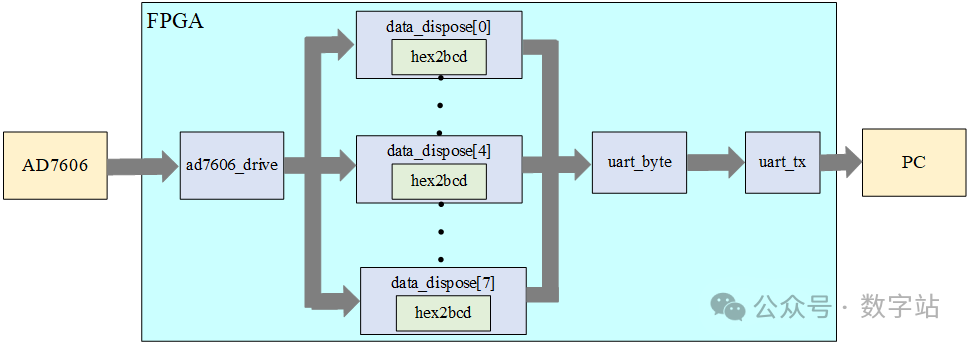
 圖1 工程框圖注意本工程ad7606驅(qū)動(dòng)雖然是200Ksps采樣率一直在采集數(shù)據(jù),但由于uart的傳輸速率過(guò)低,其實(shí)并不是采集的所有數(shù)據(jù)都會(huì)通過(guò)uart傳輸給上位機(jī),本工程只能簡(jiǎn)單采集穩(wěn)定的電壓,做做電壓表可以,并不能用來(lái)采集波形數(shù)據(jù)。
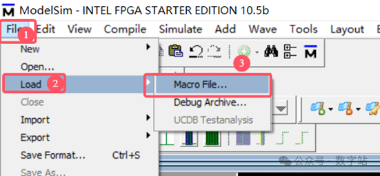
圖2 添加波形文件對(duì)應(yīng)結(jié)果如下所示,相關(guān)模塊的所有信號(hào)已經(jīng)全部添加且分類(lèi)。
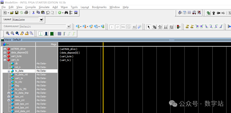
圖3 波形界面之后重新開(kāi)始仿真,點(diǎn)擊run -all即可,仿真文件運(yùn)行到$stop位置自動(dòng)停止仿真。 由于TestBench給ad7606八個(gè)通道賦值相同數(shù)據(jù),因此最終采集的數(shù)據(jù)如下圖所示。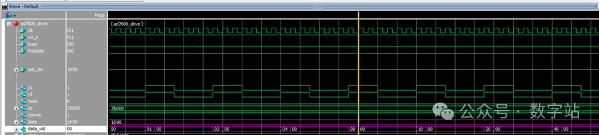
圖4 八個(gè)通道采集數(shù)據(jù)通道0的數(shù)據(jù)處理模塊如下圖所示,首先采集到的16位補(bǔ)碼數(shù)據(jù)為16’d4107,對(duì)應(yīng)原碼為15’d4107,然后計(jì)算對(duì)應(yīng)的模擬電壓((4107) / (2^15)) * 5V = 0.6266V = 626mv,最終將計(jì)算結(jié)果轉(zhuǎn)換為BCD碼,與下圖結(jié)果完全一致。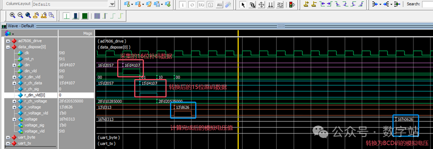
圖5 數(shù)據(jù)處理模塊仿真而uart_byte模塊把八個(gè)通道計(jì)算結(jié)果根據(jù)含義保存到對(duì)應(yīng)存儲(chǔ)器中,同時(shí)根據(jù)計(jì)數(shù)器的值向下游模塊傳輸數(shù)據(jù)。下圖所示,每當(dāng)上游模塊完成一次數(shù)據(jù)轉(zhuǎn)換,均會(huì)將存儲(chǔ)器的數(shù)據(jù)刷新。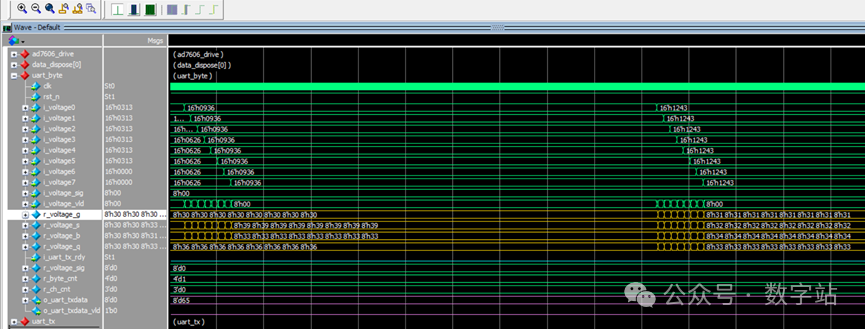
圖6 存儲(chǔ)數(shù)據(jù)傳輸數(shù)據(jù)相關(guān)的計(jì)數(shù)器如下所示,uart_tx_rdy為高電平表示uart發(fā)送模塊處于空閑狀態(tài)。為了防止uart接收端反應(yīng)不過(guò)來(lái),這里會(huì)讓空閑狀態(tài)多持續(xù)一段時(shí)間,才開(kāi)始發(fā)送下字節(jié)數(shù)據(jù)。使用計(jì)數(shù)器rdy_cnt來(lái)計(jì)數(shù)這段時(shí)間。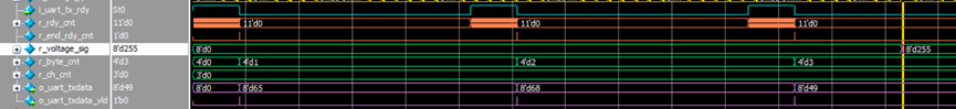
圖7 數(shù)據(jù)傳輸時(shí)序上圖中ch_cnt用來(lái)表示當(dāng)前傳輸?shù)趲讉€(gè)通道的數(shù)據(jù),而byte_cnt用來(lái)計(jì)數(shù)當(dāng)前發(fā)送該通道第幾字節(jié)數(shù)據(jù)。上圖中表示傳輸通道0第0字節(jié)數(shù)據(jù)為8’d65,對(duì)應(yīng)字符A,然后發(fā)送第1字節(jié)數(shù)據(jù)8’d68對(duì)應(yīng)D,之后傳輸通道對(duì)應(yīng)數(shù)值,一般給用戶(hù)顯示都是從1開(kāi)始的,因此8’d49表示通道1。上述三個(gè)數(shù)據(jù)顯示結(jié)果為AD1,后續(xù)仿真類(lèi)似,不再贅述。最后就是uart發(fā)送模塊,如下圖所示,發(fā)送8’h41(與8’d65相等),先發(fā)送低位數(shù)據(jù),起始位會(huì)占用一位,結(jié)果正確。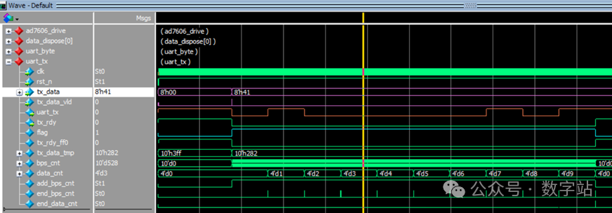
圖8 uart發(fā)送模塊仿真由于工程比較簡(jiǎn)單,因此仿真這塊做得都比較簡(jiǎn)潔,文末會(huì)提供工程,拿到后可以自行仿真。04上板實(shí)測(cè) 由于手里這塊板子的設(shè)計(jì)問(wèn)題,導(dǎo)致最終沒(méi)辦法上板,具體問(wèn)題如下所示。板子上有一個(gè)uart的公頭,如下所示。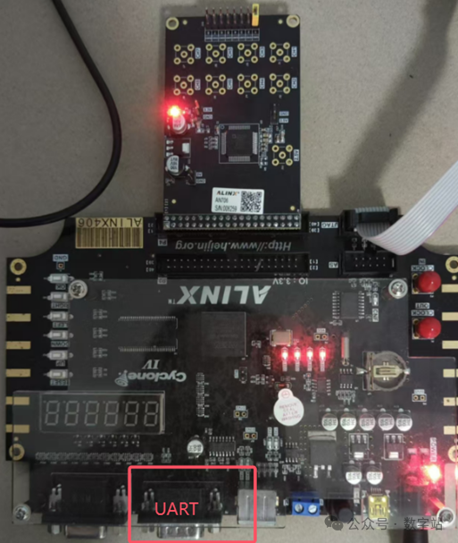
圖9 板載uart接口對(duì)應(yīng)原理圖如下所示,公頭的2腳接的是板子的uart發(fā)送引腳。
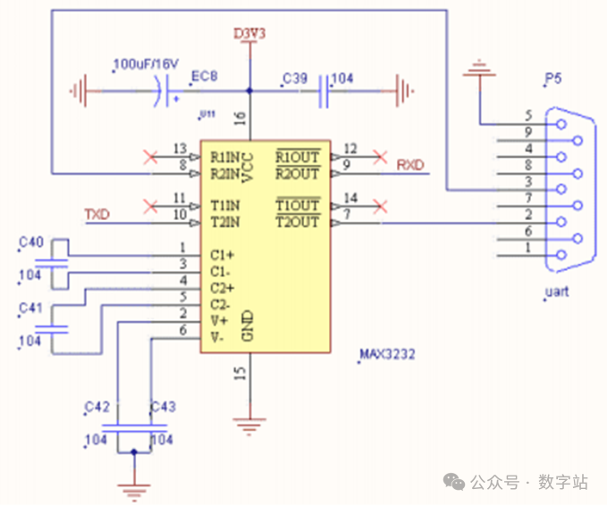
圖10 uart原理圖下圖是淘寶上該接口的線(xiàn)材接口信息,母頭線(xiàn)材2腳也是發(fā)送引腳?沒(méi)找到2腳用于接收的母頭線(xiàn)材,不知道設(shè)計(jì)這塊板子的工程師是如何想的,黑金自家也沒(méi)有賣(mài)這種線(xiàn)材。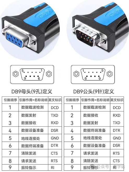
圖11 淘寶線(xiàn)材在網(wǎng)上找了一張功能類(lèi)似的截圖,上板后的結(jié)果應(yīng)該與下圖一致。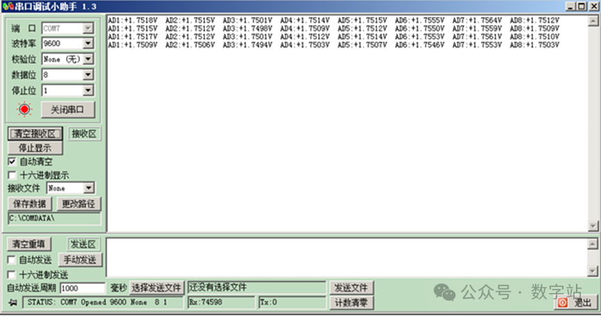
圖12 串口調(diào)試助手顯示雖然不能使用串口顯示數(shù)據(jù),但是也可以通過(guò)signal tap抓一下實(shí)測(cè)數(shù)據(jù),如果時(shí)序沒(méi)有問(wèn)題,依舊可以保證工程沒(méi)有問(wèn)題。如下圖所示,ad7606的八個(gè)通道全部懸空,然后下載程序到板子中。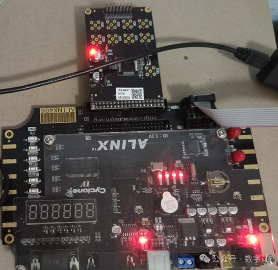
圖13 懸空ad7606八個(gè)通道輸入引腳使用signal tap抓取通道0的數(shù)據(jù),如下所示,對(duì)應(yīng)數(shù)據(jù)為16’d11857,轉(zhuǎn)換為模擬電壓為(16’d11857 / (2^15)) * 5V = 1.809V = 1809mv,與抓取的bcd碼轉(zhuǎn)換結(jié)果一致。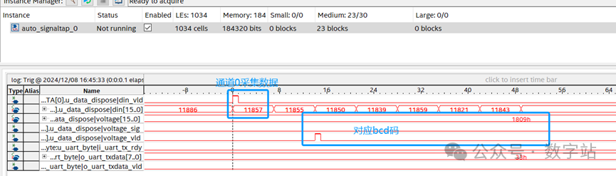
圖14 轉(zhuǎn)換時(shí)序由于uart每發(fā)送一個(gè)字節(jié)數(shù)據(jù)中間會(huì)間隔很長(zhǎng)時(shí)間,為了看到依次發(fā)送的數(shù)據(jù)對(duì)不對(duì),則需要抓取很多數(shù)據(jù),signal tap采用如下設(shè)置,只抓取o_uart_tx_vld為高電平的數(shù)據(jù),舍棄其余無(wú)用數(shù)據(jù)。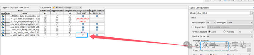
圖15 signal tap設(shè)置抓取數(shù)據(jù)如下所示,65對(duì)應(yīng)的字符A,54對(duì)應(yīng)的是通道6,由此可知第一幀數(shù)據(jù)為通道6的數(shù)據(jù),第二幀為通道7的數(shù)據(jù)。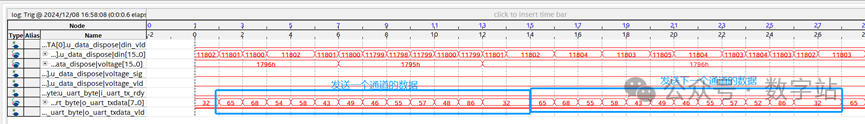
圖16 抓取發(fā)送的uart幀數(shù)據(jù)與下圖譯碼器部分代碼對(duì)比,可以驗(yàn)證上圖的正確性。
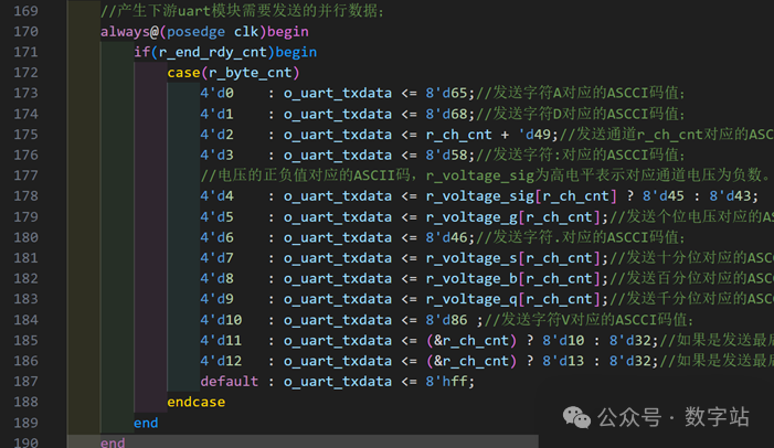
圖17 對(duì)應(yīng)譯碼最后修改signal tap抓取uart發(fā)送模塊時(shí)序,如下圖所示,發(fā)送數(shù)據(jù)為8’h2e,先發(fā)送低位數(shù)據(jù)。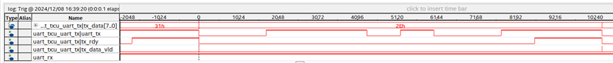
圖18 抓取uart發(fā)送模塊時(shí)序相關(guān)時(shí)序驗(yàn)證結(jié)束,整體時(shí)序是沒(méi)有問(wèn)題的,如果換個(gè)正常的uart硬件接口可以直接使用。
圖1 工程框圖注意本工程ad7606驅(qū)動(dòng)雖然是200Ksps采樣率一直在采集數(shù)據(jù),但由于uart的傳輸速率過(guò)低,其實(shí)并不是采集的所有數(shù)據(jù)都會(huì)通過(guò)uart傳輸給上位機(jī),本工程只能簡(jiǎn)單采集穩(wěn)定的電壓,做做電壓表可以,并不能用來(lái)采集波形數(shù)據(jù)。
驅(qū)動(dòng)模塊直接查看前面即可,本文不再贅述。
02程序設(shè)計(jì) 2.1數(shù)據(jù)處理模塊
AD7606模塊輸入電壓范圍是[-5,+5],本模塊功能是將16位adc補(bǔ)碼數(shù)據(jù)轉(zhuǎn)換為電壓值,最終轉(zhuǎn)換為BCD碼,便于后續(xù)傳輸給上位機(jī)顯示。如下所示,首先把補(bǔ)碼數(shù)據(jù)轉(zhuǎn)換為15位原碼數(shù)據(jù),且保存符號(hào)位。轉(zhuǎn)換為15位數(shù)據(jù)ch_data后,對(duì)應(yīng)的模擬電壓值為[0,5V],符號(hào)位決定電壓值的正負(fù)。
  always@(posedge clk or negedge rst_n)begin
    r_din_vld <= {r_din_vld[0],din_vld};
 end


  //對(duì)應(yīng)通道數(shù)據(jù)有效時(shí),把補(bǔ)碼數(shù)據(jù)轉(zhuǎn)換為原碼且保留符號(hào)位;
  always@(posedge clk or negedge rst_n)begin
   if(~rst_n)begin
      r_ch_data <=?'d0;
      r_ch_sig <= 'd0;
   end
   elseif(din_vld)begin
      r_ch_data <= din[15] ? (~din[14:0] +1) : din[14:0];
      r_ch_sig <= din[15];
   end
 end
電壓值y,ad7606采集的15位數(shù)據(jù)x的轉(zhuǎn)換關(guān)系為y=x/(2^15)。因此通過(guò)下面的方式轉(zhuǎn)換,為了保留計(jì)算精度,電壓值ch_voltage為真實(shí)值的2^15*1000倍,單位mv。ch_voltage = ch_data * 1000的計(jì)算方式采用移位和加法計(jì)算。
  //對(duì)應(yīng)通道數(shù)據(jù)乘以5000,得到真實(shí)電壓的2^15倍,單位mv;
  always@(posedge clk)begin
   if(r_din_vld[0])begin//5/32768≈0.15mv,ADC采集數(shù)據(jù)乘以0.15得電壓,0.15*2^15*1000=5000
      r_ch_voltage <= {r_ch_data,12'd0} + {r_ch_data,9'd0} + {r_ch_data,8'd0} + {r_ch_data,7'd0} + {r_ch_data,3'd0};
    end
  end
舍棄ch_voltage的低15位數(shù)據(jù),等效除以2^15,電壓值r_voltage計(jì)算就是轉(zhuǎn)換結(jié)果,單位mv。
 always@(posedge clk)begin
   r_voltage<= r_din_vld[1] ? r_ch_voltage[27:15] : r_voltage;//除以2^15次方,得到mv電壓;
   r_voltage_vld<= r_din_vld[1];
   voltage_sig<= r_ch_sig;
 end
最后通過(guò)hex2bcd模塊把轉(zhuǎn)換后的電壓值轉(zhuǎn)換為BCD碼,該模塊全部采用參數(shù)化設(shè)計(jì),前面有一篇文章也講了具體實(shí)現(xiàn)原理,有興趣的可以點(diǎn)擊查看。
//--###############################################################################################
//--#
//--# File Name  : data_dispose
//--# Designer  : 數(shù)字站
//--# Tool   : Quartus 2018.1
//--# Design Date : 2024.10.10
//--# Description :
//--# Version  : 0.0
//--# Coding scheme : UTF-8(If the Chinese comment of the file is garbled, please do not save it and check whether the file is opened in GBK encoding mode)
//--#
//--###############################################################################################
module data_dispose (
  input         clk        ,//系統(tǒng)時(shí)鐘信號(hào);
  input         rst_n       ,//系統(tǒng)復(fù)位信號(hào),低電平有效;


  input    [15:0]   din        ,//輸入數(shù)據(jù);
  input            din_vld       ,//輸入數(shù)據(jù)有效指示信號(hào),高電平有效;
  output    [15:0]   voltage       ,//輸出電壓,單位mv
  output reg           voltage_sig ='d0 ,//輸出電壓的正負(fù),低電平表示正;
  output        voltage_vld     //輸出數(shù)據(jù)有效指示信號(hào),高電平有效;
);
  reg       [1:0]     r_din_vld  ='d0 ;
  reg       [14:0]    r_ch_data      ;//
  reg       [27:0]    r_ch_voltage ='d0 ;
  reg               r_ch_sig   ='d0 ;
  reg       [12:0]    r_voltage  ='d0 ;
 reg            r_voltage_vld='d0 ;


  always@(posedge clk or negedge rst_n)begin
    r_din_vld<={r_din_vld[0],din_vld};
  end


 //對(duì)應(yīng)通道數(shù)據(jù)有效時(shí),把補(bǔ)碼數(shù)據(jù)轉(zhuǎn)換為原碼且保留符號(hào)位;
  always@(posedge clk or negedge rst_n)begin
   if(~rst_n)begin
      r_ch_data<='d0;
      r_ch_sig<='d0;
    end
   elseif(din_vld)begin
      r_ch_data<=din[15]?(~din[14:0]+1) : din[14:0];
      r_ch_sig<=din[15];
    end
  end


 //對(duì)應(yīng)通道數(shù)據(jù)乘以5000,得到真實(shí)電壓的2^15倍,單位mv;
  always@(posedge clk)begin
   if(r_din_vld[0])begin//5/32768≈0.15mv,ADC采集數(shù)據(jù)乘以0.15得電壓,0.15*2^15*1000=5000
      r_ch_voltage<={r_ch_data,12'd0}+{r_ch_data,9'd0}+{r_ch_data,8'd0}+{r_ch_data,7'd0}+{r_ch_data,3'd0};
    end
  end


 //產(chǎn)生輸出數(shù)據(jù);
  always@(posedge clk)begin
    r_voltage<=r_din_vld[1]?r_ch_voltage[27:15] : r_voltage;//除以2^15次方,得到mv電壓;
    r_voltage_vld<=r_din_vld[1];
    voltage_sig<=r_ch_sig;
  end


 //調(diào)用十六進(jìn)制轉(zhuǎn)BCD模塊,將13位十六進(jìn)制數(shù)據(jù)轉(zhuǎn)換成16位BCD碼;
  hex2bcd #(
    .IN_DATA_W (13      )//輸入數(shù)據(jù)位寬;
  )
  u_hex2bcd (
    .clk    ( clk      ),//系統(tǒng)時(shí)鐘;
    .rst_n   ( rst_n     ),//系統(tǒng)復(fù)位,低電平有效;
    .din    ( r_voltage   ),//輸入二進(jìn)制數(shù)據(jù);
    .din_vld  ( r_voltage_vld ),//輸入數(shù)據(jù)有效指示信號(hào),高電平有效;
    .rdy    (        ),//忙閑指示信號(hào),該信號(hào)高電平時(shí)才能輸入有效數(shù)據(jù);
    .dout    ( voltage    ),//輸出8421BCD碼;
    .dout_vld  ( voltage_vld  )//輸出數(shù)據(jù)有效指示信號(hào),高電平有效;
  );


endmodule
2.2
uart字節(jié)發(fā)送模塊
首先通過(guò)存儲(chǔ)器保存八路adc轉(zhuǎn)換后的bcd數(shù)據(jù),保存的時(shí)候還要將數(shù)據(jù)加48轉(zhuǎn)換為ascii編碼,因?yàn)?對(duì)應(yīng)的ascii碼對(duì)應(yīng)數(shù)值為48。
 always@(posedge clk)begin
   if(i_voltage_vld[0])begin
     r_voltage_sig[0] <= ?i_voltage_sig[0];//保存通道0的符號(hào)位;
     r_voltage_g[0] <= i_voltage0[15:12] +8'd48;//將通道0的個(gè)位數(shù)據(jù)轉(zhuǎn)換為ASCII對(duì)應(yīng)字符;
     r_voltage_s[0] <= i_voltage0[11:8] +8'd48;//將通道0的十分位數(shù)據(jù)轉(zhuǎn)換為ASCII對(duì)應(yīng)字符;
     r_voltage_b[0] <= i_voltage0[7:4] +8'd48;//將通道0的百分位數(shù)據(jù)轉(zhuǎn)換為ASCII對(duì)應(yīng)字符;
     r_voltage_q[0] <= i_voltage0[3:0] +8'd48;//將通道0的千分位數(shù)據(jù)轉(zhuǎn)換為ASCII對(duì)應(yīng)字符;
   end
 end


 always@(posedge clk)begin
   if(i_voltage_vld[1])begin
     r_voltage_sig[1] <= ?i_voltage_sig[1];//保存通道1的符號(hào)位;
     r_voltage_g[1] <= i_voltage1[15:12] +8'd48;//將通道1的個(gè)位數(shù)據(jù)轉(zhuǎn)換為ASCII對(duì)應(yīng)字符;
     r_voltage_s[1] <= i_voltage1[11:8] +8'd48;//將通道1的十分位數(shù)據(jù)轉(zhuǎn)換為ASCII對(duì)應(yīng)字符;
     r_voltage_b[1] <= i_voltage1[7:4] +8'd48;//將通道1的百分位數(shù)據(jù)轉(zhuǎn)換為ASCII對(duì)應(yīng)字符;
     r_voltage_q[1] <= i_voltage1[3:0] +8'd48;//將通道1的千分位數(shù)據(jù)轉(zhuǎn)換為ASCII對(duì)應(yīng)字符;
   end
 end


 always@(posedge clk)begin
   if(i_voltage_vld[2])begin
     r_voltage_sig[2] <= ?i_voltage_sig[2];//保存通道2的符號(hào)位;
     r_voltage_g[2] <= i_voltage2[15:12] +8'd48;//將通道2的個(gè)位數(shù)據(jù)轉(zhuǎn)換為ASCII對(duì)應(yīng)字符;
     r_voltage_s[2] <= i_voltage2[11:8] +8'd48;//將通道2的十分位數(shù)據(jù)轉(zhuǎn)換為ASCII對(duì)應(yīng)字符;
     r_voltage_b[2] <= i_voltage2[7:4] +8'd48;//將通道2的百分位數(shù)據(jù)轉(zhuǎn)換為ASCII對(duì)應(yīng)字符;
     r_voltage_q[2] <= i_voltage2[3:0] +8'd48;//將通道2的千分位數(shù)據(jù)轉(zhuǎn)換為ASCII對(duì)應(yīng)字符;
   end
 end


 always@(posedge clk)begin
   if(i_voltage_vld[3])begin
     r_voltage_sig[3] <= ?i_voltage_sig[3];//保存通道3的符號(hào)位;
     r_voltage_g[3] <= i_voltage3[15:12] +8'd48;//將通道3的個(gè)位數(shù)據(jù)轉(zhuǎn)換為ASCII對(duì)應(yīng)字符;
     r_voltage_s[3] <= i_voltage3[11:8] +8'd48;//將通道3的十分位數(shù)據(jù)轉(zhuǎn)換為ASCII對(duì)應(yīng)字符;
     r_voltage_b[3] <= i_voltage3[7:4] +8'd48;//將通道3的百分位數(shù)據(jù)轉(zhuǎn)換為ASCII對(duì)應(yīng)字符;
     r_voltage_q[3] <= i_voltage3[3:0] +8'd48;//將通道3的千分位數(shù)據(jù)轉(zhuǎn)換為ASCII對(duì)應(yīng)字符;
   end
 end


 always@(posedge clk)begin
   if(i_voltage_vld[4])begin
     r_voltage_sig[4] <= ?i_voltage_sig[4];//保存通道4的符號(hào)位;
     r_voltage_g[4] <= i_voltage4[15:12] +8'd48;//將通道4的個(gè)位數(shù)據(jù)轉(zhuǎn)換為ASCII對(duì)應(yīng)字符;
     r_voltage_s[4] <= i_voltage4[11:8] +8'd48;//將通道4的十分位數(shù)據(jù)轉(zhuǎn)換為ASCII對(duì)應(yīng)字符;
     r_voltage_b[4] <= i_voltage4[7:4] +8'd48;//將通道4的百分位數(shù)據(jù)轉(zhuǎn)換為ASCII對(duì)應(yīng)字符;
     r_voltage_q[4] <= i_voltage4[3:0] +8'd48;//將通道4的千分位數(shù)據(jù)轉(zhuǎn)換為ASCII對(duì)應(yīng)字符;
   end
 end


 always@(posedge clk)begin
   if(i_voltage_vld[5])begin
     r_voltage_sig[5] <= ?i_voltage_sig[5];//保存通道5的符號(hào)位;
     r_voltage_g[5] <= i_voltage5[15:12] +8'd48;//將通道5的個(gè)位數(shù)據(jù)轉(zhuǎn)換為ASCII對(duì)應(yīng)字符;
     r_voltage_s[5] <= i_voltage5[11:8] +8'd48;//將通道5的十分位數(shù)據(jù)轉(zhuǎn)換為ASCII對(duì)應(yīng)字符;
     r_voltage_b[5] <= i_voltage5[7:4] +8'd48;//將通道5的百分位數(shù)據(jù)轉(zhuǎn)換為ASCII對(duì)應(yīng)字符;
     r_voltage_q[5] <= i_voltage5[3:0] +8'd48;//將通道5的千分位數(shù)據(jù)轉(zhuǎn)換為ASCII對(duì)應(yīng)字符;
   end
 end


 always@(posedge clk)begin
   if(i_voltage_vld[6])begin
     r_voltage_sig[6] <= ?i_voltage_sig[6];//保存通道6的符號(hào)位;
     r_voltage_g[6] <= i_voltage6[15:12] +8'd48;//將通道6的個(gè)位數(shù)據(jù)轉(zhuǎn)換為ASCII對(duì)應(yīng)字符;
     r_voltage_s[6] <= i_voltage6[11:8] +8'd48;//將通道6的十分位數(shù)據(jù)轉(zhuǎn)換為ASCII對(duì)應(yīng)字符;
     r_voltage_b[6] <= i_voltage6[7:4] +8'd48;//將通道6的百分位數(shù)據(jù)轉(zhuǎn)換為ASCII對(duì)應(yīng)字符;
     r_voltage_q[6] <= i_voltage6[3:0] +8'd48;//將通道6的千分位數(shù)據(jù)轉(zhuǎn)換為ASCII對(duì)應(yīng)字符;
   end
 end


 always@(posedge clk)begin
   if(i_voltage_vld[7])begin
     r_voltage_sig[7] <= ?i_voltage_sig[7];//保存通道7的符號(hào)位;
     r_voltage_g[7] <= i_voltage7[15:12] +8'd48;//將通道7的個(gè)位數(shù)據(jù)轉(zhuǎn)換為ASCII對(duì)應(yīng)字符;
     r_voltage_s[7] <= i_voltage7[11:8] +8'd48;//將通道7的十分位數(shù)據(jù)轉(zhuǎn)換為ASCII對(duì)應(yīng)字符;
     r_voltage_b[7] <= i_voltage7[7:4] +8'd48;//將通道7的百分位數(shù)據(jù)轉(zhuǎn)換為ASCII對(duì)應(yīng)字符;
     r_voltage_q[7] <= i_voltage7[3:0] +8'd48;//將通道7的千分位數(shù)據(jù)轉(zhuǎn)換為ASCII對(duì)應(yīng)字符;
   end
 end
上位機(jī)顯示的格式為:ADX:±3.426V,上位機(jī)顯示的每個(gè)通道的數(shù)據(jù)需要發(fā)送11字節(jié)數(shù)據(jù),并且后續(xù)還要跟兩個(gè)空格或者回車(chē),因此每個(gè)通道需要發(fā)送13字節(jié)數(shù)據(jù)。為了便于數(shù)據(jù)接收端識(shí)別數(shù)據(jù),當(dāng)串口發(fā)送一個(gè)字節(jié)數(shù)據(jù)后,需要暫停一段時(shí)間后在發(fā)送下字節(jié)數(shù)據(jù)。因此使用一個(gè)空閑計(jì)數(shù)器對(duì)空閑時(shí)間計(jì)數(shù),停留發(fā)送2位數(shù)據(jù)才開(kāi)始下字節(jié)數(shù)據(jù)傳輸。
  always@(posedge clkornegedge rst_n)begin
    if(~rst_n)begin//初始值為0;
      r_rdy_cnt<='d0;
    end
    else if(i_uart_tx_rdy)begin
      if(r_end_rdy_cnt)
        r_rdy_cnt <= 'd0;
     else
        r_rdy_cnt<=r_rdy_cnt+'d1;
    end
  end


  always@(posedge clk)begin
    r_end_rdy_cnt <= i_uart_tx_rdy && (r_rdy_cnt == 2*BPS_CNT-2);
  end
通過(guò)兩個(gè)計(jì)數(shù)器分別記錄發(fā)送當(dāng)前通道的第幾個(gè)數(shù)據(jù)、發(fā)送的數(shù)據(jù)屬于第幾個(gè)通道。
  always@(posedge clkornegedge rst_n)begin
    if(~rst_n)begin//初始值為0;
      r_byte_cnt<='d0;
    end
    else if(r_end_rdy_cnt)begin
      if(r_byte_cnt == 12)
        r_byte_cnt <= 'd0;
     else
        r_byte_cnt<=r_byte_cnt+'d1;
    end
  end


  //一輪需要傳輸8個(gè)通道的數(shù)據(jù)到PC端,使用一個(gè)8進(jìn)制計(jì)數(shù)器對(duì)傳輸數(shù)據(jù)的通道數(shù)計(jì)數(shù);
  //當(dāng)一個(gè)通道數(shù)據(jù)傳輸結(jié)束時(shí)加1,計(jì)數(shù)器采用溢出清零;
  always@(posedge clk or negedge rst_n)begin
    if(~rst_n)begin//初始值為0;
      r_ch_cnt <= 'd0;
   end
   elseif(r_end_rdy_cnt&&(r_byte_cnt==12))begin
      r_ch_cnt<=r_ch_cnt+'d1;
    end
  end
通過(guò)譯碼器轉(zhuǎn)換數(shù)據(jù),根據(jù)字節(jié)計(jì)數(shù)器的值發(fā)送對(duì)應(yīng)的數(shù)據(jù),有部分?jǐn)?shù)據(jù)根據(jù)通道不同發(fā)送不同數(shù)據(jù)。比如通道7數(shù)據(jù)發(fā)送結(jié)束后,需要發(fā)送回車(chē)和換行字符,不需要發(fā)送空格字符。
  always@(posedge clk)begin
   if(r_end_rdy_cnt)begin
     case(r_byte_cnt)
       4'd0  : o_uart_txdata <= 8'd65;//發(fā)送字符A對(duì)應(yīng)的ASCCI碼值;
       4'd1  : o_uart_txdata <= 8'd68;//發(fā)送字符D對(duì)應(yīng)的ASCCI碼值;
       4'd2  : o_uart_txdata <= r_ch_cnt + 'd49;//發(fā)送通道r_ch_cnt對(duì)應(yīng)的ASCCI碼值;
       4'd3  : o_uart_txdata <= 8'd58;//發(fā)送字符:對(duì)應(yīng)的ASCCI碼值;
       //電壓的正負(fù)值對(duì)應(yīng)的ASCII碼,r_voltage_sig為高電平表示對(duì)應(yīng)通道電壓為負(fù)數(shù)。
       4'd4  : o_uart_txdata <= r_voltage_sig[r_ch_cnt] ? 8'd45 :8'd43;
        4'd5  : o_uart_txdata <= r_voltage_g[r_ch_cnt];//發(fā)送個(gè)位電壓對(duì)應(yīng)的ASCCI碼值;
       4'd6  : o_uart_txdata <= 8'd46;//發(fā)送字符.對(duì)應(yīng)的ASCCI碼值;
       4'd7  : o_uart_txdata <= r_voltage_s[r_ch_cnt];//發(fā)送十分位對(duì)應(yīng)的ASCCI碼值;
        4'd8  : o_uart_txdata <= r_voltage_b[r_ch_cnt];//發(fā)送百分位對(duì)應(yīng)的ASCCI碼值;
       4'd9  : o_uart_txdata <= r_voltage_q[r_ch_cnt];//發(fā)送千分位對(duì)應(yīng)的ASCCI碼值;
        4'd10  : o_uart_txdata <=?8'd86 ;//發(fā)送字符V對(duì)應(yīng)的ASCCI碼值;
        4'd11  : o_uart_txdata <= (&r_ch_cnt) ??8'd10 : 8'd32;//如果是發(fā)送最后一個(gè)通道的數(shù)據(jù),則發(fā)送換行,否則發(fā)送空格;
       4'd12  : o_uart_txdata <= (&r_ch_cnt) ? 8'd13 :8'd32;//如果是發(fā)送最后一個(gè)通道的數(shù)據(jù),則發(fā)送回車(chē),否則發(fā)送空格;
        default : o_uart_txdata <= 8'hff;
      endcase
    end
  end


  always@(posedge clk)begin
    o_uart_txdata_vld <= r_end_rdy_cnt;//生成并行數(shù)據(jù)有效指示信號(hào);
  end
該模塊參考代碼如下所示:
//--###############################################################################################
//--#
//--# File Name  : uart_byte
//--# Designer  : 數(shù)字站
//--# Tool   : Quartus 2018.1
//--# Design Date : 2024.10.10
//--# Description :
//--# Version  : 0.0
//--# Coding scheme : UTF-8(If the Chinese comment of the file is garbled, please do not save it and check whether the file is opened in GBK encoding mode)
//--#
//--###############################################################################################
module uart_byte#(
  parameter    FLCK  =   50_000_000 ,//系統(tǒng)時(shí)鐘頻率,默認(rèn)50MHZ;
  parameter    BPS   =   9600    //串口波特率;
)(
  input       clk          ,//系統(tǒng)時(shí)鐘信號(hào);
  input       rst_n         ,//系統(tǒng)復(fù)位信號(hào),低電平有效;


  input   [15:0]   i_voltage0       ,//輸入數(shù)據(jù);
  input   [15:0]   i_voltage1       ,//輸入數(shù)據(jù);
  input   [15:0]   i_voltage2       ,//輸入數(shù)據(jù);
  input   [15:0]   i_voltage3       ,//輸入數(shù)據(jù);
  input   [15:0]   i_voltage4       ,//輸入數(shù)據(jù);
  input   [15:0]   i_voltage5       ,//輸入數(shù)據(jù);
  input   [15:0]   i_voltage6       ,//輸入數(shù)據(jù);
  input   [15:0]   i_voltage7       ,//輸入數(shù)據(jù);
  input   [7:0]   i_voltage_sig      ,//各通道數(shù)據(jù)的正負(fù)數(shù)據(jù)指示信號(hào);
  input   [7:0]   i_voltage_vld      ,//輸入數(shù)據(jù)有效指示信號(hào),高電平有效;
  input            i_uart_tx_rdy      ,//uart發(fā)送模塊空閑指示信號(hào);
  output reg [7:0]     o_uart_txdata ='d0   ,//需要uart發(fā)送的并行數(shù)據(jù);
  output reg     o_uart_txdata_vld = 'd0 //需要的發(fā)送的并行數(shù)據(jù)有效指示信號(hào);
);
  localparam BPS_CNT  =   FLCK/BPS        ;//波特率為9600bit/s,當(dāng)波特率為115200bit/s時(shí),DATA_115200==434;
  localparam BPS_CNT_W =   $clog2(2*BPS_CNT-1)   ;//根據(jù)BPS_CNT調(diào)用函數(shù)自動(dòng)計(jì)算計(jì)數(shù)器bps_cnt位寬;
  reg     [7:0]     r_voltage_sig ='d0   ;
  reg     [BPS_CNT_W-1:0] r_rdy_cnt        ;
  reg             r_end_rdy_cnt      ;
  reg [7 : 0] r_voltage_g   [7 : 0]         ;
  reg [7 : 0] r_voltage_s   [7 : 0]         ;
  reg [7 : 0] r_voltage_b   [7 : 0]         ;
  reg [7 : 0] r_voltage_q   [7 : 0]         ;
  reg [3 : 0]         r_byte_cnt       ;//
  reg [2 : 0]         r_ch_cnt        ;


  /********** 存儲(chǔ)數(shù)據(jù) *************/
  always@(posedge clk)begin
    if(i_voltage_vld[0])begin
      r_voltage_sig[0] <= ?i_voltage_sig[0];//保存通道0的符號(hào)位;
      r_voltage_g[0] <= i_voltage0[15 : 12] + 8'd48;//將通道0的個(gè)位數(shù)據(jù)轉(zhuǎn)換為ASCII對(duì)應(yīng)字符;
      r_voltage_s[0] <= i_voltage0[11:8] +8'd48;//將通道0的十分位數(shù)據(jù)轉(zhuǎn)換為ASCII對(duì)應(yīng)字符;
      r_voltage_b[0] <= i_voltage0[7 : 4] + 8'd48;//將通道0的百分位數(shù)據(jù)轉(zhuǎn)換為ASCII對(duì)應(yīng)字符;
      r_voltage_q[0]<= i_voltage0[3:0] +8'd48;//將通道0的千分位數(shù)據(jù)轉(zhuǎn)換為ASCII對(duì)應(yīng)字符;
    end
  end


  always@(posedge clk)begin
    if(i_voltage_vld[1])begin
      r_voltage_sig[1] <= ?i_voltage_sig[1];//保存通道1的符號(hào)位;
      r_voltage_g[1] <= i_voltage1[15 : 12] + 8'd48;//將通道1的個(gè)位數(shù)據(jù)轉(zhuǎn)換為ASCII對(duì)應(yīng)字符;
      r_voltage_s[1] <= i_voltage1[11:8] +8'd48;//將通道1的十分位數(shù)據(jù)轉(zhuǎn)換為ASCII對(duì)應(yīng)字符;
      r_voltage_b[1] <= i_voltage1[7 : 4] + 8'd48;//將通道1的百分位數(shù)據(jù)轉(zhuǎn)換為ASCII對(duì)應(yīng)字符;
      r_voltage_q[1]<= i_voltage1[3:0] +8'd48;//將通道1的千分位數(shù)據(jù)轉(zhuǎn)換為ASCII對(duì)應(yīng)字符;
    end
  end


  always@(posedge clk)begin
    if(i_voltage_vld[2])begin
      r_voltage_sig[2] <= ?i_voltage_sig[2];//保存通道2的符號(hào)位;
      r_voltage_g[2] <= i_voltage2[15 : 12] + 8'd48;//將通道2的個(gè)位數(shù)據(jù)轉(zhuǎn)換為ASCII對(duì)應(yīng)字符;
      r_voltage_s[2] <= i_voltage2[11:8] +8'd48;//將通道2的十分位數(shù)據(jù)轉(zhuǎn)換為ASCII對(duì)應(yīng)字符;
      r_voltage_b[2] <= i_voltage2[7 : 4] + 8'd48;//將通道2的百分位數(shù)據(jù)轉(zhuǎn)換為ASCII對(duì)應(yīng)字符;
      r_voltage_q[2]<= i_voltage2[3:0] +8'd48;//將通道2的千分位數(shù)據(jù)轉(zhuǎn)換為ASCII對(duì)應(yīng)字符;
    end
  end


  always@(posedge clk)begin
    if(i_voltage_vld[3])begin
      r_voltage_sig[3] <= ?i_voltage_sig[3];//保存通道3的符號(hào)位;
      r_voltage_g[3] <= i_voltage3[15 : 12] + 8'd48;//將通道3的個(gè)位數(shù)據(jù)轉(zhuǎn)換為ASCII對(duì)應(yīng)字符;
      r_voltage_s[3] <= i_voltage3[11:8] +8'd48;//將通道3的十分位數(shù)據(jù)轉(zhuǎn)換為ASCII對(duì)應(yīng)字符;
      r_voltage_b[3] <= i_voltage3[7 : 4] + 8'd48;//將通道3的百分位數(shù)據(jù)轉(zhuǎn)換為ASCII對(duì)應(yīng)字符;
      r_voltage_q[3]<= i_voltage3[3:0] +8'd48;//將通道3的千分位數(shù)據(jù)轉(zhuǎn)換為ASCII對(duì)應(yīng)字符;
    end
  end


  always@(posedge clk)begin
    if(i_voltage_vld[4])begin
      r_voltage_sig[4] <= ?i_voltage_sig[4];//保存通道4的符號(hào)位;
      r_voltage_g[4] <= i_voltage4[15 : 12] + 8'd48;//將通道4的個(gè)位數(shù)據(jù)轉(zhuǎn)換為ASCII對(duì)應(yīng)字符;
      r_voltage_s[4] <= i_voltage4[11:8] +8'd48;//將通道4的十分位數(shù)據(jù)轉(zhuǎn)換為ASCII對(duì)應(yīng)字符;
      r_voltage_b[4] <= i_voltage4[7 : 4] + 8'd48;//將通道4的百分位數(shù)據(jù)轉(zhuǎn)換為ASCII對(duì)應(yīng)字符;
      r_voltage_q[4]<= i_voltage4[3:0] +8'd48;//將通道4的千分位數(shù)據(jù)轉(zhuǎn)換為ASCII對(duì)應(yīng)字符;
    end
  end


  always@(posedge clk)begin
    if(i_voltage_vld[5])begin
      r_voltage_sig[5] <= ?i_voltage_sig[5];//保存通道5的符號(hào)位;
      r_voltage_g[5] <= i_voltage5[15 : 12] + 8'd48;//將通道5的個(gè)位數(shù)據(jù)轉(zhuǎn)換為ASCII對(duì)應(yīng)字符;
      r_voltage_s[5] <= i_voltage5[11:8] +8'd48;//將通道5的十分位數(shù)據(jù)轉(zhuǎn)換為ASCII對(duì)應(yīng)字符;
      r_voltage_b[5] <= i_voltage5[7 : 4] + 8'd48;//將通道5的百分位數(shù)據(jù)轉(zhuǎn)換為ASCII對(duì)應(yīng)字符;
      r_voltage_q[5]<= i_voltage5[3:0] +8'd48;//將通道5的千分位數(shù)據(jù)轉(zhuǎn)換為ASCII對(duì)應(yīng)字符;
    end
  end


  always@(posedge clk)begin
    if(i_voltage_vld[6])begin
      r_voltage_sig[6] <= ?i_voltage_sig[6];//保存通道6的符號(hào)位;
      r_voltage_g[6] <= i_voltage6[15 : 12] + 8'd48;//將通道6的個(gè)位數(shù)據(jù)轉(zhuǎn)換為ASCII對(duì)應(yīng)字符;
      r_voltage_s[6] <= i_voltage6[11:8] +8'd48;//將通道6的十分位數(shù)據(jù)轉(zhuǎn)換為ASCII對(duì)應(yīng)字符;
      r_voltage_b[6] <= i_voltage6[7 : 4] + 8'd48;//將通道6的百分位數(shù)據(jù)轉(zhuǎn)換為ASCII對(duì)應(yīng)字符;
      r_voltage_q[6]<= i_voltage6[3:0] +8'd48;//將通道6的千分位數(shù)據(jù)轉(zhuǎn)換為ASCII對(duì)應(yīng)字符;
    end
  end


  always@(posedge clk)begin
    if(i_voltage_vld[7])begin
      r_voltage_sig[7] <= ?i_voltage_sig[7];//保存通道7的符號(hào)位;
      r_voltage_g[7] <= i_voltage7[15 : 12] + 8'd48;//將通道7的個(gè)位數(shù)據(jù)轉(zhuǎn)換為ASCII對(duì)應(yīng)字符;
      r_voltage_s[7] <= i_voltage7[11:8] +8'd48;//將通道7的十分位數(shù)據(jù)轉(zhuǎn)換為ASCII對(duì)應(yīng)字符;
      r_voltage_b[7] <= i_voltage7[7 : 4] + 8'd48;//將通道7的百分位數(shù)據(jù)轉(zhuǎn)換為ASCII對(duì)應(yīng)字符;
      r_voltage_q[7]<= i_voltage7[3:0] +8'd48;//將通道7的千分位數(shù)據(jù)轉(zhuǎn)換為ASCII對(duì)應(yīng)字符;
    end
  end


  /********* 發(fā)送數(shù)據(jù) ************/
  //空閑計(jì)數(shù)器,發(fā)送一字節(jié)數(shù)據(jù)后,暫停一段時(shí)間在發(fā)送下字節(jié)數(shù)據(jù);
  always@(posedge clk or negedge rst_n)begin
    if(~rst_n)begin//初始值為0;
      r_rdy_cnt <= 'd0;
    end
   elseif(i_uart_tx_rdy)begin
     if(r_end_rdy_cnt)
        r_rdy_cnt <=?'d0;
      else
        r_rdy_cnt <= r_rdy_cnt + 'd1;
    end
  end


  always@(posedge clk)begin
    r_end_rdy_cnt <= i_uart_tx_rdy && (r_rdy_cnt ==?2*BPS_CNT-2);
  end


  //每個(gè)通道需要發(fā)送13字節(jié)串口數(shù)據(jù)到PC端,使用一個(gè)13進(jìn)制計(jì)數(shù)器對(duì)發(fā)送數(shù)據(jù)計(jì)數(shù);
  //當(dāng)下游模塊空閑時(shí)表示發(fā)送完成1字節(jié)數(shù)據(jù),計(jì)數(shù)器加1.
  always@(posedge clkornegedge rst_n)begin
   if(~rst_n)begin//初始值為0;
      r_byte_cnt <=?'d0;
    end
    else if(r_end_rdy_cnt)begin
      if(r_byte_cnt == 12)
        r_byte_cnt <= 'd0;
     else
        r_byte_cnt <= r_byte_cnt +?'d1;
    end
  end


  //一輪需要傳輸8個(gè)通道的數(shù)據(jù)到PC端,使用一個(gè)8進(jìn)制計(jì)數(shù)器對(duì)傳輸數(shù)據(jù)的通道數(shù)計(jì)數(shù);
  //當(dāng)一個(gè)通道數(shù)據(jù)傳輸結(jié)束時(shí)加1,計(jì)數(shù)器采用溢出清零;
  always@(posedge clk or negedge rst_n)begin
    if(~rst_n)begin//初始值為0;
      r_ch_cnt <= 'd0;
    end
   elseif(r_end_rdy_cnt && (r_byte_cnt ==12))begin
      r_ch_cnt <= r_ch_cnt +?'d1;
    end
  end


  //產(chǎn)生下游uart模塊需要發(fā)送的并行數(shù)據(jù);
  always@(posedge clk)begin
    if(r_end_rdy_cnt)begin
      case(r_byte_cnt)
        4'd0  : o_uart_txdata <=?8'd65;//發(fā)送字符A對(duì)應(yīng)的ASCCI碼值;
        4'd1  : o_uart_txdata <=?8'd68;//發(fā)送字符D對(duì)應(yīng)的ASCCI碼值;
        4'd2  : o_uart_txdata <= r_ch_cnt +?'d49;//發(fā)送通道r_ch_cnt對(duì)應(yīng)的ASCCI碼值;
        4'd3  : o_uart_txdata <=?8'd58;//發(fā)送字符:對(duì)應(yīng)的ASCCI碼值;
        //電壓的正負(fù)值對(duì)應(yīng)的ASCII碼,r_voltage_sig為高電平表示對(duì)應(yīng)通道電壓為負(fù)數(shù)。
        4'd4  : o_uart_txdata <= r_voltage_sig[r_ch_cnt] ??8'd45 : 8'd43;
       4'd5  : o_uart_txdata <= r_voltage_g[r_ch_cnt];//發(fā)送個(gè)位電壓對(duì)應(yīng)的ASCCI碼值;
        4'd6  : o_uart_txdata <=?8'd46;//發(fā)送字符.對(duì)應(yīng)的ASCCI碼值;
        4'd7  : o_uart_txdata <= r_voltage_s[r_ch_cnt];//發(fā)送十分位對(duì)應(yīng)的ASCCI碼值;
       4'd8  : o_uart_txdata <= r_voltage_b[r_ch_cnt];//發(fā)送百分位對(duì)應(yīng)的ASCCI碼值;
        4'd9  : o_uart_txdata <= r_voltage_q[r_ch_cnt];//發(fā)送千分位對(duì)應(yīng)的ASCCI碼值;
       4'd10  : o_uart_txdata <= 8'd86 ;//發(fā)送字符V對(duì)應(yīng)的ASCCI碼值;
       4'd11  : o_uart_txdata <= (&r_ch_cnt) ? 8'd10:8'd32;//如果是發(fā)送最后一個(gè)通道的數(shù)據(jù),則發(fā)送換行,否則發(fā)送空格;
        4'd12  : o_uart_txdata <= (&r_ch_cnt) ??8'd13 : 8'd32;//如果是發(fā)送最后一個(gè)通道的數(shù)據(jù),則發(fā)送回車(chē),否則發(fā)送空格;
        default : o_uart_txdata <=?8'hff;
      endcase
    end
  end


  always@(posedge clk)begin
    o_uart_txdata_vld <= r_end_rdy_cnt;//生成并行數(shù)據(jù)有效指示信號(hào);
  end


endmodule
uart發(fā)送模塊依舊使用以前模塊,前文詳細(xì)講解過(guò)uart接收模塊全模式設(shè)計(jì)方式,本文就不再贅述,參考代碼如下所示:
//--###############################################################################################
//--#
//--# File Name : uart_tx
//--# Designer : 數(shù)字站
//--# Tool : Quartus 2018.1
//--# Design Date : 2024.10.10
//--# Description :
//--# Version : 0.0
//--# Coding scheme : UTF-8(If the Chinese comment of the file is garbled, please do not save it and check whether the file is opened in GBK encoding mode)
//--#
//--###############################################################################################
module uart_tx
parameter FLCK = 50_000_000 ,//系統(tǒng)時(shí)鐘頻率,默認(rèn)50MHZ;
parameter BPS = 9600 ,//串口波特率;
parameter DATA_W = 8 ,//發(fā)送數(shù)據(jù)位數(shù)以及輸出數(shù)據(jù)位寬;
parameter START_W = 1 ,//1位起始位;
parameter CHECK_W = 2'b00 ,//校驗(yàn)位,2'b00代表無(wú)校驗(yàn)位,2'b01表示奇校驗(yàn),2'b10表示偶校驗(yàn),2'b11按無(wú)校驗(yàn)處理。
parameter STOP_W = 2'b01 //停止位,2'b01表示1位停止位,2'b10表示2位停止位,2'b11表示1.5位停止位;
)(
input clk ,//系統(tǒng)工作時(shí)鐘50MHZ
input rst_n ,//系統(tǒng)復(fù)位信號(hào),低電平有效
input [DATA_W-1:0] tx_data ,//數(shù)據(jù)輸入信號(hào)。
input tx_data_vld ,//數(shù)據(jù)有效指示信號(hào),高電平有效。
output reg uart_tx ,//uart接口數(shù)據(jù)輸出信號(hào)。
output reg tx_rdy //模塊忙閑指示信號(hào);
);
localparam BPS_CNT = FLCK/BPS ;//波特率為9600bit/s,當(dāng)波特率為115200bit/s時(shí),DATA_115200==434;
localparam BPS_CNT_W = $clog2(BPS_CNT-1);//根據(jù)BPS_CNT調(diào)用函數(shù)自動(dòng)計(jì)算計(jì)數(shù)器bps_cnt位寬;
localparam DATA_CNT = START_W + DATA_W + (^CHECK_W) + ((STOP_W==2'b11) ?2: STOP_W);//計(jì)數(shù)器計(jì)數(shù)值;
localparam DATA_CNT_W= $clog2(DATA_CNT-1);//根據(jù)計(jì)數(shù)器cnt的值,利用函數(shù)自動(dòng)計(jì)算此計(jì)數(shù)器的位寬;
reg flag ;
reg tx_rdy_ff0 ;//
reg [DATA_CNT-1:0] tx_data_tmp ;
reg [BPS_CNT_W-1:0] bps_cnt ;
reg [DATA_CNT_W-1:0]data_cnt ;
wire add_bps_cnt ;
wire end_bps_cnt ;
wire end_data_cnt ;
/*發(fā)送一位數(shù)據(jù)所需要的時(shí)間*/
always @(posedge clkornegedge rst_n)begin
if(!rst_n)begin
bps_cnt <= {{BPS_CNT_W}{1'b0}};
end
elseif(add_bps_cnt)begin
if(end_bps_cnt || end_data_cnt)
bps_cnt <= {{BPS_CNT_W}{1'b0}};
else
bps_cnt <= bps_cnt + {{{BPS_CNT_W-1}{1'b0}},1'b1};
end
end
assign add_bps_cnt = flag;
assign end_bps_cnt = add_bps_cnt && bps_cnt == BPS_CNT-1;
/*發(fā)送一組數(shù)據(jù)所用時(shí)間*/
always@(posedge clkornegedge rst_n)begin
if(rst_n==1'b0)begin//
data_cnt <= {{DATA_CNT}{1'b0}};
end
elseif(end_data_cnt)begin
data_cnt <= {{DATA_CNT}{1'b0}};
end
elseif(end_bps_cnt)begin
data_cnt <= data_cnt + {{{DATA_CNT-1}{1'b0}},1'b1};
end
end
//根據(jù)停止位的不同生成不同的計(jì)數(shù)器結(jié)束條件;
generate
if(STOP_W ==2'b11)//1.5位停止位,因?yàn)镃NT_NUM沒(méi)有包含起始位,所以要等計(jì)數(shù)器計(jì)數(shù)到CNT_NUM時(shí)清零;
assign end_data_cnt = data_cnt == DATA_CNT-1&& add_bps_cnt && bps_cnt == BPS_CNT/2-1;
else//停止位為1位或者2位;
assign end_data_cnt = end_bps_cnt && data_cnt == DATA_CNT-1;
endgenerate
//這個(gè)期間UART在發(fā)送數(shù)據(jù);
always@(posedge clkornegedge rst_n)begin
if(rst_n==1'b0)begin
flag <=?1'b0;
end
elseif(tx_data_vld)begin
flag <=?1'b1;
end
elseif(end_data_cnt)begin
flag <=?1'b0;
end
end
//UART模塊處于忙時(shí)期,收到上游模塊數(shù)據(jù)或者正在處理上游模塊所發(fā)數(shù)據(jù);
always@(*)begin
if(tx_data_vld || flag)begin
tx_rdy =1'b0;
end
elsebegin
tx_rdy =1'b1;
end
end
always@(posedge clk)begin
tx_rdy_ff0 <= tx_rdy;
end
//將上游模塊所發(fā)并行數(shù)據(jù)轉(zhuǎn)化為串行數(shù)據(jù);
generate
if(CHECK_W ==2'b01)begin//奇校驗(yàn);
always@(posedge clkornegedge rst_n)begin
if(rst_n==1'b0)begin
tx_data_tmp <= {{DATA_CNT+1}{1'b1}};
end
elseif(tx_rdy_ff0 && tx_data_vld)begin
tx_data_tmp <= {{{STOP_W}{1'b1}},~(^tx_data),tx_data,{{START_W}{1'b0}}};
end
end
end
elseif(CHECK_W ==2'b10)begin//偶校驗(yàn)
always@(posedge clkornegedge rst_n)begin
if(rst_n==1'b0)begin
tx_data_tmp <= {{DATA_CNT+1}{1'b1}};
end
elseif(tx_rdy_ff0 && tx_data_vld)begin
tx_data_tmp <= {{{STOP_W}{1'b1}},(^tx_data),tx_data,{{START_W}{1'b0}}};
end
end
end
elsebegin//無(wú)校驗(yàn)
always@(posedge clkornegedge rst_n)begin
if(rst_n==1'b0)begin
tx_data_tmp <= {{DATA_CNT+1}{1'b1}};
end
elseif(tx_rdy_ff0 && tx_data_vld)begin
tx_data_tmp <= {{{STOP_W}{1'b1}},tx_data,{{START_W}{1'b0}}};
end
end
end
endgenerate
//將串行數(shù)據(jù)按9600波特率送出,先發(fā)低位;
always@(posedge clkornegedge rst_n)begin
if(rst_n==1'b0)begin
uart_tx <=?1'b1;
end
elseif(add_bps_cnt && bps_cnt==0)begin
uart_tx <= tx_data_tmp[data_cnt];
end
end
endmodule
2.3
頂層模塊
頂層模塊如下所示,單獨(dú)列出來(lái)是因?yàn)榇a使用for循環(huán)例化了8個(gè)通道的數(shù)據(jù)處理模塊。參考代碼如下所示:
//--###############################################################################################
//--#
//--# File Name : top
//--# Designer :
//--# Tool : Quartus 2018.1
//--# Design Date : 2024.10.10
//--# Description :
//--# Version : 0.0
//--# Coding scheme : UTF-8(If the Chinese comment of the file is garbled, please do not save it and check whether the file is opened in GBK encoding mode)
//--#
//--###############################################################################################
module top
parameter FLCK = 100_000_000 ,//系統(tǒng)時(shí)鐘頻率,默認(rèn)50MHZ;
parameter BPS = 115200 ,//串口波特率;
parameter UART_DATA_W = 8 ,//發(fā)送數(shù)據(jù)位數(shù)以及輸出數(shù)據(jù)位寬;
parameter START_W = 1 ,//1位起始位;
parameter CHECK_W = 2'b00 ,//校驗(yàn)位,2'b00代表無(wú)校驗(yàn)位,2'b01表示奇校驗(yàn),2'b10表示偶校驗(yàn),2'b11按無(wú)校驗(yàn)處理。
parameter STOP_W = 2'b01 //停止位,2'b01表示1位停止位,2'b10表示2位停止位,2'b11表示1.5位停止位;
)(
input clk ,//系統(tǒng)時(shí)鐘,50MHz;
input rst_n ,//系統(tǒng)復(fù)位,低電平有效;
input busy ,//轉(zhuǎn)換完成指示信號(hào),下降沿有效;
input frstdata ,//指示采集到的第一個(gè)數(shù)據(jù);
input [15:0] adc_din ,//AD7606所采集到的十六位數(shù)據(jù)信號(hào);
input uart_rx ,
output cs ,//AD7606片選信號(hào),讀數(shù)據(jù)時(shí)拉低;
output rd ,//AD7606讀使能信號(hào),讀數(shù)據(jù)時(shí)拉低,下降沿時(shí)AD7606將數(shù)據(jù)發(fā)送到數(shù)據(jù)線(xiàn)上,上升沿時(shí)可以讀出數(shù)據(jù);
output reset ,//AD7606復(fù)位信號(hào),高電平有效,每次復(fù)位至少拉高50ns;
output [2:0] os ,//AD7606過(guò)采樣模式信號(hào),默認(rèn)不使用過(guò)采樣;
output convst ,//AD7606采樣啟動(dòng)信號(hào),無(wú)效時(shí)高電平,采樣計(jì)數(shù)器完成時(shí)拉低兩個(gè)時(shí)鐘;
output uart_tx //uart接口數(shù)據(jù)輸出信號(hào)。
);
wire clk_100m ;//鎖相環(huán)輸出時(shí)鐘;
wire [15:0] w_7606_data ;//AD7606通道采集的補(bǔ)碼數(shù)據(jù);
wire [7:0] w_7606_data_vld ;//指示AD7606輸出的數(shù)據(jù)來(lái)自哪個(gè)數(shù)據(jù)通道;
wire [15:0] w_voltage [7:0] ;//輸出電壓,單位mv
wire [7:0] w_voltage_sig ;//輸出電壓的正負(fù),低電平表示正;
wire [7:0] w_voltage_vld ;//輸出數(shù)據(jù)有效指示信號(hào),高電平有效;
wire [UART_DATA_W-1:0] w_tx_data ;//數(shù)據(jù)輸入信號(hào)。
wire w_tx_data_vld ;//數(shù)據(jù)有效指示信號(hào),高電平有效。
wire w_tx_rdy ;//模塊忙閑指示信號(hào);
//例化鎖相環(huán)
pllu_pll(
.areset ( ~rst_n ),
.inclk0(clk ),
.c0 (clk_100m )
);
//例化ad7606驅(qū)動(dòng)模塊
ad7606_drive
.FCLK ( FLCK ),//系統(tǒng)時(shí)鐘頻率,單位Hz,默認(rèn)100MHz;
.SMAPLE (200_000 )//AD7606采樣頻率,單位Hz,默認(rèn)200KHz;
)
u_ad7606_drive (
.clk ( clk_100m ),//系統(tǒng)時(shí)鐘,100MHz;
.rst_n ( rst_n ),//系統(tǒng)復(fù)位,低電平有效;
.busy ( busy ),//轉(zhuǎn)換完成指示信號(hào),下降沿有效;
.frstdata ( frstdata ),//指示采集到的第一個(gè)數(shù)據(jù);
.adc_din ( adc_din ),//AD7606所采集到的十六位數(shù)據(jù)信號(hào);
.cs ( cs ),//AD7606片選信號(hào),讀數(shù)據(jù)時(shí)拉低;
.rd ( rd ),//AD7606讀使能信號(hào),讀數(shù)據(jù)時(shí)拉低,下降沿時(shí)AD7606將數(shù)據(jù)發(fā)送到數(shù)據(jù)線(xiàn)上,上升沿時(shí)可以讀出數(shù)據(jù);
.reset ( reset ),//AD7606復(fù)位信號(hào),高電平有效,每次復(fù)位至少拉高50ns;
.os ( os ),//AD7606過(guò)采樣模式信號(hào),默認(rèn)不使用過(guò)采樣;
.convst ( convst ),//AD7606采樣啟動(dòng)信號(hào),無(wú)效時(shí)高電平,采樣計(jì)數(shù)器完成時(shí)拉低兩個(gè)時(shí)鐘;
.data ( w_7606_data ),//AD7606采集到的數(shù)據(jù).數(shù)據(jù)均為補(bǔ)碼;
.data_vld ( w_7606_data_vld )//指示AD7606輸出的數(shù)據(jù)來(lái)自哪個(gè)數(shù)據(jù)通道;
);
genvar i;
//使用for循環(huán)例化8個(gè)數(shù)據(jù)處理模塊,將ad7606采集的數(shù)據(jù)轉(zhuǎn)換為bcd碼的mv電壓;
generate
for(i=0; i<8; i=i+1)begin : DATA
data_disposeu_data_dispose(
.clk ( clk_100m ),//系統(tǒng)時(shí)鐘信號(hào);
.rst_n (rst_n ),//系統(tǒng)復(fù)位信號(hào),低電平有效;
.din (w_7606_data ),//輸入數(shù)據(jù);
.din_vld (w_7606_data_vld[i]),//輸入數(shù)據(jù)有效指示信號(hào),高電平有效;
.voltage (w_voltage[i] ),//輸出電壓,單位mv
.voltage_sig (w_voltage_sig[i] ),//輸出電壓的正負(fù),低電平表示正;
.voltage_vld (w_voltage_vld[i] )//輸出數(shù)據(jù)有效指示信號(hào),高電平有效;
);
end
endgenerate
//例化數(shù)據(jù)處理模塊
uart_byte
.FLCK ( FLCK ),//系統(tǒng)時(shí)鐘頻率,默認(rèn)50MHZ;
.BPS ( BPS )//串口波特率;
)
u_uart_byte(
.clk ( clk_100m ),//系統(tǒng)時(shí)鐘信號(hào);
.rst_n ( rst_n ),//系統(tǒng)復(fù)位信號(hào),低電平有效;
.i_voltage0 ( w_voltage[0] ),//輸入數(shù)據(jù);
.i_voltage1 ( w_voltage[1] ),//輸入數(shù)據(jù);
.i_voltage2 ( w_voltage[2] ),//輸入數(shù)據(jù);
.i_voltage3 ( w_voltage[3] ),//輸入數(shù)據(jù);
.i_voltage4 ( w_voltage[4] ),//輸入數(shù)據(jù);
.i_voltage5 ( w_voltage[5] ),//輸入數(shù)據(jù);
.i_voltage6 ( w_voltage[6] ),//輸入數(shù)據(jù);
.i_voltage7 ( w_voltage[7] ),//輸入數(shù)據(jù);
.i_voltage_sig ( w_voltage_sig ),//各通道數(shù)據(jù)的正負(fù)數(shù)據(jù)指示信號(hào);
.i_voltage_vld ( w_voltage_vld ),//輸入數(shù)據(jù)有效指示信號(hào),高電平有效;
.i_uart_tx_rdy ( w_tx_rdy ),//uart發(fā)送模塊空閑指示信號(hào);
.o_uart_txdata ( w_tx_data ),//需要uart發(fā)送的并行數(shù)據(jù);
.o_uart_txdata_vld ( w_tx_data_vld )//需要的發(fā)送的并行數(shù)據(jù)有效指示信號(hào);
);
//例化串口發(fā)送模塊;
uart_tx
.FLCK ( FLCK ),//系統(tǒng)時(shí)鐘頻率,默認(rèn)50MHZ;
.BPS ( BPS ),//串口波特率;
.DATA_W ( UART_DATA_W ),//發(fā)送數(shù)據(jù)位數(shù)以及輸出數(shù)據(jù)位寬;
.START_W ( START_W ),//1位起始位;
.CHECK_W ( CHECK_W ),//校驗(yàn)位,2'b00代表無(wú)校驗(yàn)位,2'b01表示奇校驗(yàn),2'b10表示偶校驗(yàn),2'b11按無(wú)校驗(yàn)處理。
.STOP_W ( STOP_W )//停止位,2'b01表示1位停止位,2'b10表示2位停止位,2'b11表示1.5位停止位;
)
u_uart_tx (
.clk ( clk_100m ),//系統(tǒng)工作時(shí)鐘50MHZ
.rst_n ( rst_n ),//系統(tǒng)復(fù)位信號(hào),低電平有效
.tx_data ( w_tx_data ),//數(shù)據(jù)輸入信號(hào)。
.tx_data_vld( w_tx_data_vld ),//數(shù)據(jù)有效指示信號(hào),高電平有效。
.uart_tx ( uart_tx ),//uart接口數(shù)據(jù)輸出信號(hào)。
.tx_rdy ( w_tx_rdy )//模塊忙閑指示信號(hào);
);
endmodule
03工程仿真 仿真的數(shù)據(jù)來(lái)源依舊使用前文ad7606驅(qū)動(dòng)模塊的測(cè)試數(shù)據(jù),對(duì)應(yīng)參考代碼如下所示。
`timescale1ns/1ns
//--###############################################################################################
//--#
//--# File Name  : test
//--# Designer  : 數(shù)字站
//--# Tool   : Quartus 2018.1
//--# Design Date : 2024.11.3
//--# Description :
//--# Version  : 0.0
//--# Coding scheme : GBK(If the Chinese comment of the file is garbled, please do not save it and check whether the file is opened in GBK encoding mode)
//--#
//--###############################################################################################
module test();
  localparam     CYCLE = 20  ;//系統(tǒng)時(shí)鐘周期,單位ns,默認(rèn)10ns;
  localparam     RST_TIME= 10  ;//系統(tǒng)復(fù)位持續(xù)時(shí)間,默認(rèn)10個(gè)系統(tǒng)時(shí)鐘周期;


  reg         clk    = 'd1   ;//系統(tǒng)時(shí)鐘,100MHz;
  reg         rst_n   = 'd1   ;//系統(tǒng)復(fù)位,高電平有效;
  reg         busy    = 'd0   ;//轉(zhuǎn)換完成指示信號(hào),下降沿有效;
  reg         frstdata  = 'd0   ;//指示采集到的第一個(gè)數(shù)據(jù);
  reg   [15:0]  adc_din  = 'd0   ;//AD7606所采集到的十六位數(shù)據(jù)信號(hào);


  wire        cs           ;//AD7606片選信號(hào),讀數(shù)據(jù)時(shí)拉低;
  wire        rd           ;//AD7606讀使能信號(hào),讀數(shù)據(jù)時(shí)拉低,下降沿時(shí)AD7606將數(shù)據(jù)發(fā)送到數(shù)據(jù)線(xiàn)上,上升沿時(shí)可以讀出數(shù)據(jù);
  wire        reset          ;//AD7606復(fù)位信號(hào),高電平有效,每次復(fù)位至少拉高50ns;
  wire  [2:0]   os           ;//AD7606過(guò)采樣模式信號(hào),默認(rèn)不使用過(guò)采樣;
  wire        convst         ;//AD7606采樣啟動(dòng)信號(hào),無(wú)效時(shí)高電平,采樣計(jì)數(shù)器完成時(shí)拉低兩個(gè)時(shí)鐘;
  wire        uart_tx         ;//uart接口數(shù)據(jù)輸出信號(hào)。


 //待測(cè)試的模塊例化
  top u_top (
    .clk    ( clk    ),//系統(tǒng)時(shí)鐘,50MHz;
    .rst_n   ( rst_n   ),//系統(tǒng)復(fù)位,低電平有效;
    .busy    ( busy   ),//轉(zhuǎn)換完成指示信號(hào),下降沿有效;
    .frstdata  ( frstdata ),//指示采集到的第一個(gè)數(shù)據(jù);
    .adc_din  ( adc_din  ),//AD7606所采集到的十六位數(shù)據(jù)信號(hào);
    .cs     ( cs    ),//AD7606片選信號(hào),讀數(shù)據(jù)時(shí)拉低;
    .rd     ( rd    ),//AD7606讀使能信號(hào),讀數(shù)據(jù)時(shí)拉低,下降沿時(shí)AD7606將數(shù)據(jù)發(fā)送到數(shù)據(jù)線(xiàn)上,上升沿時(shí)可以讀出數(shù)據(jù);
    .reset   ( reset   ),//AD7606復(fù)位信號(hào),高電平有效,每次復(fù)位至少拉高50ns;
    .os     ( os    ),//AD7606過(guò)采樣模式信號(hào),默認(rèn)不使用過(guò)采樣;
    .convst   ( convst  ),//AD7606采樣啟動(dòng)信號(hào),無(wú)效時(shí)高電平,采樣計(jì)數(shù)器完成時(shí)拉低兩個(gè)時(shí)鐘;
    .uart_tx  ( uart_tx  )//uart接口數(shù)據(jù)輸出信號(hào)。
  );


  initial begin
    forever #(CYCLE/2) clk = ~clk;//生成本地時(shí)鐘50M
  end


 //產(chǎn)生復(fù)位信號(hào)
  localparamDATA_NUM=400;
  reg [15:0] stimulus[1:DATA_NUM];
  integerPattern;
  initial begin
   $readmemb("waveform_bit.txt",stimulus);//從外部TX文件(waveform_bit.txt)讀入數(shù)據(jù)作為測(cè)試激勵(lì);
   Pattern=1;
    #1;
    rst_n=1'b0;
    #(CYCLE*RST_TIME);
    rst_n=1'b1;
   repeat(20)@(posedge clk);
   repeat(DATA_NUM)begin
      @(posedge convst);
      busy<=1'b1;
     repeat(30)@(posedge clk);
      busy<=1'b0;
      @(negedge rd);
      adc_din<=stimulus[Pattern];
     Pattern<=Pattern+1;
      @(posedge clk);
    end
   repeat(20)@(posedge clk);//延遲20個(gè)時(shí)鐘周期;
   $stop;
  end


endmodule
采用Quartus 18.1和modelsim聯(lián)合仿真,打開(kāi)modelsim仿真界面wave后,先刪除該界面自動(dòng)添加的信號(hào)。然后如下圖所示,添加我提前設(shè)置好的波形文件wave.do。圖2 添加波形文件對(duì)應(yīng)結(jié)果如下所示,相關(guān)模塊的所有信號(hào)已經(jīng)全部添加且分類(lèi)。
圖3 波形界面之后重新開(kāi)始仿真,點(diǎn)擊run -all即可,仿真文件運(yùn)行到$stop位置自動(dòng)停止仿真。 由于TestBench給ad7606八個(gè)通道賦值相同數(shù)據(jù),因此最終采集的數(shù)據(jù)如下圖所示。
圖4 八個(gè)通道采集數(shù)據(jù)通道0的數(shù)據(jù)處理模塊如下圖所示,首先采集到的16位補(bǔ)碼數(shù)據(jù)為16’d4107,對(duì)應(yīng)原碼為15’d4107,然后計(jì)算對(duì)應(yīng)的模擬電壓((4107) / (2^15)) * 5V = 0.6266V = 626mv,最終將計(jì)算結(jié)果轉(zhuǎn)換為BCD碼,與下圖結(jié)果完全一致。
圖5 數(shù)據(jù)處理模塊仿真而uart_byte模塊把八個(gè)通道計(jì)算結(jié)果根據(jù)含義保存到對(duì)應(yīng)存儲(chǔ)器中,同時(shí)根據(jù)計(jì)數(shù)器的值向下游模塊傳輸數(shù)據(jù)。下圖所示,每當(dāng)上游模塊完成一次數(shù)據(jù)轉(zhuǎn)換,均會(huì)將存儲(chǔ)器的數(shù)據(jù)刷新。
圖6 存儲(chǔ)數(shù)據(jù)傳輸數(shù)據(jù)相關(guān)的計(jì)數(shù)器如下所示,uart_tx_rdy為高電平表示uart發(fā)送模塊處于空閑狀態(tài)。為了防止uart接收端反應(yīng)不過(guò)來(lái),這里會(huì)讓空閑狀態(tài)多持續(xù)一段時(shí)間,才開(kāi)始發(fā)送下字節(jié)數(shù)據(jù)。使用計(jì)數(shù)器rdy_cnt來(lái)計(jì)數(shù)這段時(shí)間。
圖7 數(shù)據(jù)傳輸時(shí)序上圖中ch_cnt用來(lái)表示當(dāng)前傳輸?shù)趲讉€(gè)通道的數(shù)據(jù),而byte_cnt用來(lái)計(jì)數(shù)當(dāng)前發(fā)送該通道第幾字節(jié)數(shù)據(jù)。上圖中表示傳輸通道0第0字節(jié)數(shù)據(jù)為8’d65,對(duì)應(yīng)字符A,然后發(fā)送第1字節(jié)數(shù)據(jù)8’d68對(duì)應(yīng)D,之后傳輸通道對(duì)應(yīng)數(shù)值,一般給用戶(hù)顯示都是從1開(kāi)始的,因此8’d49表示通道1。上述三個(gè)數(shù)據(jù)顯示結(jié)果為AD1,后續(xù)仿真類(lèi)似,不再贅述。最后就是uart發(fā)送模塊,如下圖所示,發(fā)送8’h41(與8’d65相等),先發(fā)送低位數(shù)據(jù),起始位會(huì)占用一位,結(jié)果正確。
圖8 uart發(fā)送模塊仿真由于工程比較簡(jiǎn)單,因此仿真這塊做得都比較簡(jiǎn)潔,文末會(huì)提供工程,拿到后可以自行仿真。04上板實(shí)測(cè) 由于手里這塊板子的設(shè)計(jì)問(wèn)題,導(dǎo)致最終沒(méi)辦法上板,具體問(wèn)題如下所示。板子上有一個(gè)uart的公頭,如下所示。
圖9 板載uart接口對(duì)應(yīng)原理圖如下所示,公頭的2腳接的是板子的uart發(fā)送引腳。
圖10 uart原理圖下圖是淘寶上該接口的線(xiàn)材接口信息,母頭線(xiàn)材2腳也是發(fā)送引腳?沒(méi)找到2腳用于接收的母頭線(xiàn)材,不知道設(shè)計(jì)這塊板子的工程師是如何想的,黑金自家也沒(méi)有賣(mài)這種線(xiàn)材。
圖11 淘寶線(xiàn)材在網(wǎng)上找了一張功能類(lèi)似的截圖,上板后的結(jié)果應(yīng)該與下圖一致。
圖12 串口調(diào)試助手顯示雖然不能使用串口顯示數(shù)據(jù),但是也可以通過(guò)signal tap抓一下實(shí)測(cè)數(shù)據(jù),如果時(shí)序沒(méi)有問(wèn)題,依舊可以保證工程沒(méi)有問(wèn)題。如下圖所示,ad7606的八個(gè)通道全部懸空,然后下載程序到板子中。
圖13 懸空ad7606八個(gè)通道輸入引腳使用signal tap抓取通道0的數(shù)據(jù),如下所示,對(duì)應(yīng)數(shù)據(jù)為16’d11857,轉(zhuǎn)換為模擬電壓為(16’d11857 / (2^15)) * 5V = 1.809V = 1809mv,與抓取的bcd碼轉(zhuǎn)換結(jié)果一致。
圖14 轉(zhuǎn)換時(shí)序由于uart每發(fā)送一個(gè)字節(jié)數(shù)據(jù)中間會(huì)間隔很長(zhǎng)時(shí)間,為了看到依次發(fā)送的數(shù)據(jù)對(duì)不對(duì),則需要抓取很多數(shù)據(jù),signal tap采用如下設(shè)置,只抓取o_uart_tx_vld為高電平的數(shù)據(jù),舍棄其余無(wú)用數(shù)據(jù)。
圖15 signal tap設(shè)置抓取數(shù)據(jù)如下所示,65對(duì)應(yīng)的字符A,54對(duì)應(yīng)的是通道6,由此可知第一幀數(shù)據(jù)為通道6的數(shù)據(jù),第二幀為通道7的數(shù)據(jù)。
圖16 抓取發(fā)送的uart幀數(shù)據(jù)與下圖譯碼器部分代碼對(duì)比,可以驗(yàn)證上圖的正確性。
圖17 對(duì)應(yīng)譯碼最后修改signal tap抓取uart發(fā)送模塊時(shí)序,如下圖所示,發(fā)送數(shù)據(jù)為8’h2e,先發(fā)送低位數(shù)據(jù)。
圖18 抓取uart發(fā)送模塊時(shí)序相關(guān)時(shí)序驗(yàn)證結(jié)束,整體時(shí)序是沒(méi)有問(wèn)題的,如果換個(gè)正常的uart硬件接口可以直接使用。
聲明:本文內(nèi)容及配圖由入駐作者撰寫(xiě)或者入駐合作網(wǎng)站授權(quán)轉(zhuǎn)載。文章觀點(diǎn)僅代表作者本人,不代表電子發(fā)燒友網(wǎng)立場(chǎng)。文章及其配圖僅供工程師學(xué)習(xí)之用,如有內(nèi)容侵權(quán)或者其他違規(guī)問(wèn)題,請(qǐng)聯(lián)系本站處理。
舉報(bào)投訴
-
adc
+關(guān)注
關(guān)注
99文章
6638瀏覽量
548247 -
串口
+關(guān)注
關(guān)注
14文章
1583瀏覽量
78636 -
上位機(jī)
+關(guān)注
關(guān)注
27文章
960瀏覽量
55585
原文標(biāo)題:fpga通過(guò)uart向上位機(jī)傳輸ad7606采集數(shù)據(jù)
文章出處:【微信號(hào):HXSLH1010101010,微信公眾號(hào):FPGA技術(shù)江湖】歡迎添加關(guān)注!文章轉(zhuǎn)載請(qǐng)注明出處。
發(fā)布評(píng)論請(qǐng)先 登錄
相關(guān)推薦
熱點(diǎn)推薦
基于zigbee網(wǎng)絡(luò)的數(shù)據(jù)采集與上位機(jī)系統(tǒng)
1、本項(xiàng)目可實(shí)現(xiàn)對(duì)工業(yè)、農(nóng)業(yè)數(shù)據(jù)的采集和遠(yuǎn)程數(shù)據(jù)傳輸與監(jiān)控;2、采用zigbee模塊制作節(jié)點(diǎn)網(wǎng)絡(luò),實(shí)現(xiàn)數(shù)據(jù)的遠(yuǎn)程傳輸。3、
發(fā)表于 10-17 23:12
【OK210申請(qǐng)】無(wú)線(xiàn)數(shù)據(jù)傳輸模塊設(shè)計(jì)
和單片機(jī)的接口電路。(3) 編寫(xiě)控制無(wú)線(xiàn)數(shù)據(jù)傳輸器件進(jìn)行數(shù)據(jù)。目標(biāo):(1) 單片機(jī)系統(tǒng):通過(guò)串口傳輸
發(fā)表于 07-24 10:39
【CANNON申請(qǐng)】?jī)蓧K板之間藍(lán)牙數(shù)據(jù)傳輸
申請(qǐng)理由:一直從事單片機(jī)的數(shù)據(jù)通信,想實(shí)現(xiàn)一次藍(lán)牙的數(shù)據(jù)傳輸功能。項(xiàng)目描述:兩塊板實(shí)現(xiàn)數(shù)據(jù)傳輸。比如,A板采集芯片內(nèi)部溫度,
發(fā)表于 01-19 16:05
ADC信號(hào)采集與串口傳輸的疑問(wèn)
用msp430f149采集心電信號(hào),然后通過(guò)串口傳輸給上位機(jī)。假設(shè)設(shè)置采樣率為200Hz,1s內(nèi)能采集
發(fā)表于 05-08 12:52
請(qǐng)問(wèn)怎么將SD卡中存儲(chǔ)的數(shù)據(jù)通過(guò)GPRS傳輸到電腦上顯示?
,認(rèn)為不能及時(shí)的將傳感器實(shí)時(shí)采集的數(shù)據(jù)通過(guò)GPRS傳輸給電腦(因?yàn)镚PRS數(shù)據(jù)傳輸所需要的時(shí)間大于傳感器
發(fā)表于 04-30 02:54
請(qǐng)問(wèn)ov2640采集單張照片怎么通過(guò)wifi傳輸給上位機(jī)?
如題,stm32f1控制ov2640采集單張圖片利用wifi發(fā)送給上位機(jī),wifi是sta透?jìng)髂J剑壳?b class='flag-5'>上位機(jī)接收到的
發(fā)表于 05-09 06:06
無(wú)線(xiàn)數(shù)據(jù)傳輸模塊的實(shí)際應(yīng)用
數(shù)據(jù)傳輸模塊的實(shí)際應(yīng)用一、智能安防安防是物聯(lián)網(wǎng)的一大應(yīng)用市場(chǎng),傳統(tǒng)安防對(duì)人員的依賴(lài)性比較大,非常耗費(fèi)人力,而智能安防能夠通過(guò)設(shè)備實(shí)現(xiàn)智能判斷。目前,智能安防最核心的部分在于智能安防系統(tǒng),該系統(tǒng)中應(yīng)用無(wú)線(xiàn)
發(fā)表于 06-18 04:21
串口線(xiàn)采集數(shù)據(jù),波形圖表顯示怎么操作?
我想用labview顯示下位機(jī)的波形。做了一個(gè)測(cè)試程序。 Stm32做了一個(gè)dac輸出1k的正弦波,做了一個(gè)adc(10khz的速度)來(lái)采集這個(gè)正弦波,
發(fā)表于 08-30 10:51
stm32的幾種數(shù)據(jù)傳輸總結(jié)
引言在一般的項(xiàng)目開(kāi)發(fā)過(guò)程中,往往需要兩塊或以上單片機(jī)進(jìn)行通信完成數(shù)據(jù)傳輸,例如四旋翼無(wú)人機(jī)在飛行過(guò)程中無(wú)線(xiàn)傳輸數(shù)據(jù)回到地面站,治療儀器需要實(shí)時(shí)將
發(fā)表于 08-23 07:32
如何利用單片機(jī)和上位機(jī)進(jìn)行大量的數(shù)據(jù)傳輸呢
如何利用單片機(jī)和上位機(jī)進(jìn)行大量的數(shù)據(jù)傳輸呢?傳輸過(guò)程中會(huì)遇到哪些問(wèn)題呢?
發(fā)表于 12-09 06:03
數(shù)據(jù)傳輸速率是什么意思
數(shù)據(jù)傳輸速率是什么意思
數(shù)據(jù)傳輸速率是通過(guò)信道每秒可傳輸的數(shù)字信息量的量度。數(shù)據(jù)傳輸速率也稱(chēng)為吞吐率。
發(fā)表于 03-18 14:45
?5074次閱讀
基于單片機(jī)89c51的浮點(diǎn)型數(shù)據(jù)及串口通信整型的處理和發(fā)送
在做下位機(jī)通信時(shí)往往會(huì)用到串口,包括下位機(jī)將數(shù)據(jù)傳輸給上位機(jī)
發(fā)表于 09-05 17:50
?6次下載

如何在單片機(jī)串口中發(fā)送超過(guò)8位的數(shù)據(jù)
在做下位機(jī)通信時(shí)往往會(huì)用到串口,包括下位機(jī)將數(shù)據(jù)傳輸給上位機(jī)
發(fā)表于 04-16 17:28
?5次下載
高速數(shù)據(jù)傳輸藍(lán)牙雙模方案
高速數(shù)據(jù)傳輸透?jìng)髂J绞且环N直接傳輸模式,數(shù)據(jù)通過(guò)藍(lán)牙模塊傳輸,不需要特定命令。 主控制器通過(guò)串口


 工商網(wǎng)監(jiān)
評(píng)論