") 制作FPV競(jìng)速四旋翼直升機(jī) 這些是必須的
制作FPV競(jìng)速四旋翼直升機(jī) 這些是必須的

By Terry Dunnon March 23, 2015 at 1 a.m.Building an FPV Racing Quadcopter, Part 1
Racing quadrotors have captured the interest of a lot of people. They’re fast, nimble, and tough. Best of all, having a First Person View (FPV) system installed lets you get a sense of what it’s like to be onboard your speed machine. In the past, we’ve presented a video of Norm building a racing quad with the help of Carlos Puertolas (Charpu). We’ve also given you a buyer’s guide that outlined all the equipment you need for your own racing quad. This week, I’ve prepared a four-part series that will cover each aspect of getting a racing quad built and flight-tested:
Part 1: Frame AssemblyPart 2: Flight Controller SetupPart 3: Configuring the FPV SystemPart 4: Flight Testing and Tuning
A friendly reminder: if you are new to multi-rotors, racing quads are a horrible place to start. Get yourself something a little more sedate to help you learn the basics. Once you’ve honed your flying skills, racing quads are much more practical and enjoyable.
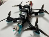
Frame AssemblyThe quad that I’ll be building for this series is a Strider Mini Quad provided by Red Rotor RC. The Strider is a 250mm-class ship with a carbon fiber frame. There are a few features on the Strider that negate purchasing some of the common components found on racing quads. The Power Distribution Board (PDB), lost-model alarm, and On-Screen Display (OSD) are all integrated into the frame itself. This saves you the cost of buying those components separately, as well as the hassle of installing them.
THE STRIDER FROM RED ROTOR RC IS A 250MM RACING QUAD WITH A CARBON FIBER FRAME. AS YOU CAN SEE, THERE AREN’T MANY PARTS. THE INCLUDED HARDWARE HAS BEEN SORTED IN AN ICE TRAY FOR EASY IDENTIFICATION.
Red Rotor provides an online assembly manual, so make sure you are using the latest version. In addition to what’s provided in the kit, you will need a few basic tools and supplies: metric Allen wrenches, zip ties, heatshrink tubing, soldering iron, etc…pretty basic stuff. To prepare for the build, I sorted all of the included hardware in a plastic ice tray. There are four different length screws in the kit and this helped me keep them all distinct.
The first few steps of assembly are very straightforward. They involve fastening the bottom plate of the frame to the center plate. They’re simple assembly tasks with nuts, bolts and spacers. All of the parts lined up perfectly, so things progressed quickly.
A WELCOME FEATURE OF THE STRIDER IS THAT IT HAS SEVERAL ELECTRONIC COMPONENTS INTEGRATED INTO THE FRAME, SO THEY DO NOT HAVE TO BE PURCHASED AND INSTALLED SEPARATELY.
Before mounting the arms to the quad you’ll have to decide whether you will use 5”-diameter props or 6”. This really boils down to the motors you’ve chosen. Each arm has two mounting options to accommodate the appropriate prop. If you are unsure, which prop you’ll be using, just use the 6” locations to mount the arms. You can always move them later. Note that the motor mounting holes on the arms are not symmetrical. You’ll have to pay attention to this to ensure that the wires from the motor are aligned with the arm.
THE STRIDER’S ARMS CAN BE INSTALLED IN EITHER OF TWO CONFIGURATIONS. HERE, THEY ARE INSTALLED IN THE INNERMOST POSITION TO ACCOMMODATE 5” PROPELLERS.
I knew that I would start out using 5” props, so I mounted my arms in the innermost location. It is worth noting that the arms can also be folded to reduce the Strider’s footprint for transport. You just have to loosen two screws for each arm to release them for folding. The same folding action can help absorb energy in a crash to prevent damage to the frame.
MotorsThe motors, I chose for this quad are SunnySky 2204 2300kV brushless units from Buddy RC. You may notice that you can buy a “CCW” version of the same motor. The only difference is that the CCW version has reverse threads on the prop shaft. The CCW motor is actually meant to rotate clockwise (as viewed from above). This helps to prevent the aerodynamic drag of the prop from loosening the nut that holds it on. Since you’ll have two motors turning clockwise and two counter-clockwise, you can buy two of each motor type. I just bought four of the standard type, thinking that I’d have to be an idiot to fly with loose prop nuts. Well, it turns out I’m an idiot, but I digress -- more on that when I cover flight testing.
I USED SUNNY SKY 2204 2300KV MOTORS IN THE STRIDER. THE ‘CCW” VERSIONS OF THIS MOTOR HAVE REVERSE THREADS ON THE PROP SHAFT TO HELP PREVENT CLOCKWISE ROTATING PROPS FROM COMING LOOSE. IT’S HANDY, BUT NOT A NECESSITY.
The bolt pattern on the motors fit the holes in the quad arms perfectly. I used the screws included with the motors to mount them to the arms. A drop of blue Loctite thread-locker on every motor screw helps to ensure that none of them vibrate loose.
Electronic Speed ControlsAt the same time that I purchased the motors, I also picked up four Velotech Magic 12-amp Electronic Speed Controls (ESCs). The ESCs are available with or without a Battery Eliminator Circuit (BEC). The BEC allows the flight battery to also power the receiver and flight controller (and the servos if any were present). You only need one ESC to BEC. In fact, sometimes having multiple BECs in parallel causes problems. The simplest path is to buy one ESC with BEC and 3 without. Just make sure that they are all the same base ESC.
ON THREE OF THE ESCS, I DISABLED THE BEC CIRCUIT BY REMOVING THE RED WIRE FROM THE RECEIVER PLUG AND INSULATING IT WITH HEATSHRINK TUBING.
All four of my Magic ESCs have BEC, so I disabled it on three of the units. This is easily done by removing the red wire from the ESC’s receiver plug. I used heatshrink tubing to insulate the removed pin on each of the three affected ESCs.
AS SMALL AS THE VELOTECH MAGIC ESCS ARE, THEY WERE STILL A TIGHT FIT IN THE STRIDER.
The Velotech ESCs were a little longer than the units shown in the Strider manual, so they were a pretty tight fit in the indicated locations. I was able to squeeze them into place and secure them with zip ties.
The PDB is integrated into the center plate of the quad. There are solder pads on the top and bottom side of the plate for attaching the power leads of each ESC as well as a pigtail for connection to the flight battery. I decided to place all of the solder connections on the top side of the plate. Knowing that space would be at a premium in this area, I carefully routed each power lead from the ESCs to the intended solder location and cut them to the precise lengths needed.
TAKE YOUR TIME WHEN SOLDERING THE POWER LEADS TO THE PDB. IT DOESN’T HAVE TO BE PRETTY, BUT YOUR JOINTS MUST BE CLEAN AND SOLID.
If you are new to soldering, you may find this job difficult. There are a lot of different wires to manage and a few physical obstacles are in the way. These joints are critical, so it is important to do a good job (no cold joints). Also, since the carbon fiber frame is electrically conductive, you have to make sure that your work is clean with no solder bridges to the chassis. Ask for help if necessary and make sure you get it right. For what it’s worth, I used a 25-watt iron with a wedge tip.
I SHORTENED THE MOTOR LEADS FROM THE ESCS BEFORE SOLDERING, BUT LEFT ENOUGH SLACK TO BE ABLE TO MOVE THE FRAME ARMS TO THEIR OUTER POSITIONS.
You’ll also have to solder the motor leads from the ESCs to the motors. Again, I trimmed the ESC wires so that they could be routed cleanly to the motors. In this case, I cut the wires a little long in case I ever extend the arms to the 6”-prop positions. It’s always better to shorten the ESC wires rather than the motor wires. The motors are wound with magnet wire that has a non-conductive coating on it. If you cut the wires, you have to scrape off this coating before the wire will take solder. It’s a pain.
ONCE THE ESCS ARE IN PLACE, THERE ARE A LOT OF WIRES TO BE DEALT WITH. THEY ALL HAVE A PURPOSE AND A PLACE TO BE.
For each motor, I soldered the three wires but did not insulate them initially. I checked to make sure that each motor rotated in the correct direction first. You could do this by sequentially attaching each ESC to the throttle channel of your radio, but I think it’s easier to use a servo tester. If a motor spun in the wrong direction, I swapped two of the motor leads (any two will do). Once I had the motors spinning correctly, I insulated the solder joints with heatshrink tubing.
Radio Receiver/TransmitterIt takes a 4-channel radio to fly the Strider, but you’ll be better off with at least 6 channels. Those extra two channels allow you to select different flight modes (they define how the quad reacts to control inputs), and also control lights and the alarm.
The example in the directions shows installation of a FrSky Taranis radio system. A lot of flyers like the Taranis for racing quads because it enables a simple 3-wire (CPPM) connection to the flight controller and some receivers feature a built-in RSSI (Received Signal Strength Indication) output. With RSSI, you can overlay a graphic strength indicator on your video screen that tells you if your radio signal is getting weak. That’s handy data for long-distance flyers.
I decided to use my Futaba 7C radio for the Strider. I have nothing against the Taranis, but I’ve used the 7C for years and it’s never given me an ounce of trouble. There’s a lot to be said for confidence in your gear. The tradeoff is that my Futaba R617FS receiver requires a few more wires to connect it to the flight controller, which is mostly a matter of space. While the R617FS does not have RSSI output, it can be added with a relatively simple modification. Since I don’t plan to do any long-distance flights with the Strider, I’m not sure that I’ll ever bother.
11
The path I’ve chosen requires more wires than other methods. I could reduce wires by using a CPPM receiver and/or trimming the receiver leads from the ESCs. Not only could I have shortened the leads, but I could have completely removed the positive and negative wires from the three ESCs with disabled BECs. Even with all of this extraneous wire, I still did not have any trouble fitting it all within the confines of the frame. In that regard, I think that my build is a worst-case example wiring-wise and it all panned out without any difficulty.
Before mounting the receiver to the frame, I decided to install and configure the flight controller, an Open Pilot CC3D . The Strider frame has nylon studs which are spaced perfectly to hold the CC3D. There is a printed indicator on the flight controller showing which side should face the front of the quad, but this configuration obscured the mini-USB port on the board. So I turned the CC3D 90-degrees and made an adjustment during setup of the board’s firmware to compensate. More about that is coming soon.
Although, there is a slight bit more to complete on the frame, it happens just before flying. So this is a good stopping point. In Part Two, I will cover wiring and configuration of the CC3D flight controller.
Terry spent 15 years as an engineer at the Johnson Space Center. He is now a freelance writer living in Lubbock, Texas. Follow Terry on Twitter: @weirdflight
制作FPV競(jìng)速四旋翼直升機(jī) building特里Pd降低一個(gè)FPV賽車直升機(jī),1
賽車quadrotors已經(jīng)俘獲了很多人的興趣。它們是快速、靈活和堅(jiān)韌的。最重要的是,有一個(gè)第一人稱視角(FPV)系統(tǒng)的安裝可以讓你得到的感覺(jué)就像是在你的機(jī)器的速度。在過(guò)去,我們已經(jīng)提出了一種視頻規(guī)范建立一個(gè)賽車四與卡洛斯puertolas幫助(charpu)。我們也給了你一個(gè)買家的指南,概述了所有你需要為你自己的賽車。這個(gè)星期,我準(zhǔn)備了一四部分的系列,將得到一個(gè)賽車四建造和飛行測(cè)試的各個(gè)方面:< / P > 1部分:框架assemblypart 2:飛行控制器setuppart 3:配置FPV系統(tǒng)4:飛行測(cè)試和tuning
一個(gè)友好的提醒:如果你是新的多轉(zhuǎn)子比賽開(kāi)始,四周是一個(gè)可怕的地方。給自己一點(diǎn)幫助你學(xué)習(xí)基礎(chǔ)知識(shí)更穩(wěn)重。一旦你磨練你的飛行技巧,賽車的四周是更實(shí)際、更愉快。
框架組件
四,我會(huì)為這個(gè)系列的建筑是由紅色轉(zhuǎn)子RC提供黽迷你四。黽是一個(gè)碳纖維車架250mm的班船。有幾個(gè)特點(diǎn)在黽否定購(gòu)買一些常見(jiàn)的成分在賽車四周發(fā)現(xiàn)。配電板(PDB),失去了模型的報(bào)警和屏幕顯示(OSD)都集成到框架本身。這節(jié)省了你購(gòu)買這些組件分開(kāi)的成本,以及安裝的麻煩。
the黽由紅轉(zhuǎn)RC是250mm賽車四個(gè)碳纖維框架。正如你所看到的,沒(méi)有多少零件。在一個(gè)冰盤上已經(jīng)有了一個(gè)很容易辨認(rèn)的硬件。除了什么試劑盒提供的,你需要一些基本的工具和用品:度量艾倫扳手,拉鏈領(lǐng)帶,heatshrink油管,烙鐵,等很基本的東西。為了準(zhǔn)備建造,我把所有的包括在一個(gè)塑料托盤中的硬件進(jìn)行排序。工具箱里有四個(gè)不同長(zhǎng)度的螺絲釘,這幫我把它們放在不同的情況。它們涉及到中心板的底部板的緊固。他們是簡(jiǎn)單的裝配任務(wù),螺母,螺栓和墊片。所有的零件排列完美,所以事情進(jìn)展很快。
a歡迎的特征是它的黽若干電子元件集成到框架中,這樣就不需要購(gòu)買和安裝分開(kāi)。
在安裝武器的四你必須決定是否將使用5“直徑的道具或6”。這真的歸結(jié)為你選擇的馬達(dá)。每個(gè)手臂有2個(gè)安裝選項(xiàng),以適應(yīng)適當(dāng)?shù)闹еH绻悴淮_定,你將使用哪一個(gè)道具,只要用6個(gè)“地點(diǎn)”來(lái)安裝武器。你可以隨時(shí)移動(dòng)他們。注意手臂上的電機(jī)安裝孔不是對(duì)稱的。你得注意這個(gè)保證電機(jī)的電線與手臂對(duì)齊。
the黽的武器可以安裝在兩配置之一。在這里,它們被安裝在容納5“螺旋槳最里面的位置。
我知道我會(huì)開(kāi)始使用5”的道具,所以我裝在里面的位置,我的手臂。值得注意的是,武器也可以折疊以減少運(yùn)輸Strider的足跡。你只需要放松兩只手臂,釋放他們的折疊螺釘。同樣的折疊動(dòng)作可以幫助吸收碰撞能量以防止損壞的幀。
電機(jī)
馬達(dá),我選擇了這四是華科2204 2300kv刷單位從好友RC。你可能注意到了,你可以買一個(gè)“同電動(dòng)機(jī)正版”。唯一不同的是,CCW版本有反向螺紋的傳動(dòng)軸。CCW電機(jī)實(shí)際上是意味著順時(shí)針轉(zhuǎn)動(dòng)(從上面看)。這有助于防止支柱的氣動(dòng)阻力,從松動(dòng)的螺母,認(rèn)為它在。既然你有2個(gè)馬達(dá),順時(shí)針和2逆時(shí)針,你可以買2個(gè)馬達(dá)的類型。我只買了四的標(biāo)準(zhǔn)型,認(rèn)為我必須是一個(gè)傻瓜飛與松散的支柱螺母。哦,原來(lái)我是個(gè)傻瓜,但我離題了,更多的是當(dāng)我蓋的飛行測(cè)試。
i在黽用晴朗的天空2204 2300kv電機(jī)。“公約”這一運(yùn)動(dòng)的版本有反向螺紋的支撐軸順時(shí)針旋轉(zhuǎn)的道具來(lái)幫助防止松動(dòng)。這很方便,但不是必要的,“汽車上的螺栓模式適合于完美的四臂上的孔。我用的螺絲,將其安裝到手臂的螺絲。一滴藍(lán)色的樂(lè)泰螺紋鎖每個(gè)電機(jī)螺釘有助于確保他們沒(méi)有振動(dòng)松動(dòng)。
電子速度控制
我同時(shí)購(gòu)買了汽車,我還買了四velotech魔法12與電子速度控制(ESC)。胚胎干細(xì)胞可帶或不帶電池消除器電路(BEC)。BEC允許飛行的電池也功率接收器和飛行控制器(和舵機(jī)如果任何人出席)。你只需要一個(gè)ESC BEC。事實(shí)上,有時(shí)有多個(gè)BEC并行問(wèn)題的原因。最簡(jiǎn)單的途徑是購(gòu)買一個(gè)ESC BEC和3無(wú)。只是確保他們都是同一基地ESC。
on三,我禁用了BEC電路由接收堵紅色電線絕緣與heatshrink油管。
我的魔法ESC四都有BEC,所以我禁用它三的單位。這是由ESC的接收器堵紅色線容易做。我用heatshrink油管絕緣刪除引腳在每個(gè)三受影響的胚胎干細(xì)胞。
as小的velotech神奇的胚胎干細(xì)胞,他們?nèi)栽邳w緊配合。
的velotech胚胎干細(xì)胞比在黽手冊(cè)所示的單位時(shí)間長(zhǎng)一點(diǎn),所以他們?cè)谥甘镜奈恢煤芫o。我能擠到的地方,用拉鎖固定。
PDB融入中心板的四。在頂部和底部連接電源板的每側(cè)導(dǎo)致ESC以及連接電池引線焊盤的飛行。我決定把所有的焊接連接在板的頂部。知道空間將在這一地區(qū)的地價(jià),我小心地掩飾每個(gè)電源引線從ESCs的焊接位置和減少他們所需的精確長(zhǎng)度。
take時(shí)間當(dāng)焊接功率導(dǎo)致PDB。它不需要漂亮,但你的關(guān)節(jié)必須是干凈的和固體的,如果你是新的焊接,你可能會(huì)發(fā)現(xiàn)這個(gè)工作很難。有很多不同的導(dǎo)線來(lái)管理和一些物理障礙的方式。這些關(guān)節(jié)都是很重要的,所以做一個(gè)好工作(沒(méi)有冷關(guān)節(jié))是很重要的。此外,由于碳纖維框架是導(dǎo)電的,你必須確保你的工作是干凈的沒(méi)有焊料橋的底盤。如果需要的話,請(qǐng)尋求幫助,確保你得到它的權(quán)利。值得一提的是,我用一個(gè)25瓦的用鐵楔尖。
i縮短電機(jī)引線焊接前的胚胎干細(xì)胞,但留下足夠的松弛能夠移動(dòng)架臂外位置。
你也可以焊接電機(jī)引線從胚胎干細(xì)胞對(duì)電機(jī)。再次,我修剪了ESC線以便排干凈的汽車。在這種情況下,我把電線切成了一點(diǎn),以防我將手臂伸到6個(gè)“支柱位置”。它總是更好地縮短ESC線而不是汽車電線。電機(jī)用電磁線的傷口,它有一個(gè)非導(dǎo)電涂層。如果你切斷了電線,你得先把這層涂層刮去,才可以帶焊。這是一種痛苦。
once ESCs在的地方,有很多的電線要處理。他們都有一個(gè)目的和一個(gè)地方。
每個(gè)電機(jī),我焊接三線但沒(méi)有使它們最初。我檢查以確保每個(gè)電機(jī)在正確方向上旋轉(zhuǎn)。你可以通過(guò)按順序?qū)⒚總€(gè)ESC你收音機(jī)的節(jié)流通道,但我認(rèn)為這是一個(gè)容易使用的伺服試驗(yàn)機(jī)。如果電機(jī)在錯(cuò)誤的方向旋轉(zhuǎn),我換了兩個(gè)電機(jī)的導(dǎo)線(任意兩都行)。一旦我有電機(jī)旋轉(zhuǎn)正確,我絕緣的焊點(diǎn)heatshrink油管。
無(wú)線電接收機(jī)/發(fā)射機(jī)
需要4通道無(wú)線電飛黽,但你會(huì)變得更好,至少有6個(gè)頻道。這些額外的兩通道讓你選擇不同的飛行模式(它們定義了四如何控制輸入的反應(yīng)),并控制燈和報(bào)警。
例子的方向顯示一frsky Taranis廣播系統(tǒng)安裝。很多傳單像賽車四周的Taranis因?yàn)樗挂粋€(gè)簡(jiǎn)單的3線(CPPM)連接到飛行控制器和接收器具有一個(gè)內(nèi)置的RSSI(接收信號(hào)強(qiáng)度指示)輸出。與RSSI,你可以在你的屏幕上的圖形強(qiáng)度指標(biāo)疊加,告訴你如果你的無(wú)線電信號(hào)越來(lái)越弱。這是長(zhǎng)途飛行方便數(shù)據(jù)。
我決定使用雙葉7C無(wú)線電為黽。我不反對(duì)Taranis,但我已經(jīng)使用多年的7C和它從來(lái)沒(méi)有給我麻煩一點(diǎn)。有很多要說(shuō)的信心在你的齒輪。權(quán)衡的是,我的大r617fs接收機(jī)需要幾根線連接到控制器,主要是一個(gè)空間。而r617fs沒(méi)有RSSI輸出,也可以加一個(gè)相對(duì)簡(jiǎn)單的修改。因?yàn)槲也淮蛩阕鋈魏伍L(zhǎng)途飛行的鳥(niǎo),我不知道我會(huì)不會(huì)打擾。
我已經(jīng)選擇的道路比其他方法需要更多的線。我可以用CPPM接收和/或修剪接收機(jī)的引線從胚胎干細(xì)胞減少導(dǎo)線。我不僅可以縮短這一線索,但我可以完全刪除的
-
直升機(jī)
+關(guān)注
關(guān)注
1文章
170瀏覽量
21434
發(fā)布評(píng)論請(qǐng)先 登錄
全新Tattu R-Line 6.0版本|FPV電池的大膽進(jìn)化!

如何為樹(shù)莓派 FPV 戰(zhàn)斗無(wú)人機(jī)構(gòu)建自動(dòng)駕駛儀的“眼睛”!

使用 Betaflight 和樹(shù)莓派實(shí)現(xiàn) FPV 無(wú)人機(jī)自主飛行!
一文詳解!獲取135部資質(zhì),沃飛長(zhǎng)空如何布局低空?qǐng)鼍叭A路徑

200-300MHz FPV四葉草全向天線:通信質(zhì)量的方案
深圳安騰納天線|100-200MHz FPV四葉草全向天線:無(wú)死角信號(hào)傳輸
低空安防革命:鐳神智能激光雷達(dá)矩陣破解空域安全世紀(jì)難題

旋極星源榮登2024年四川省新經(jīng)濟(jì)企業(yè)100強(qiáng)榜單
開(kāi)源項(xiàng)目!打造一款FPV頭部追蹤相機(jī),讓你仿佛置身遙控車之中!
為何無(wú)人機(jī)領(lǐng)域廣泛采用PX4作為核心控制平臺(tái)
壓電疊堆功率放大器在直升機(jī)機(jī)身振動(dòng)研究中的應(yīng)用


 工商網(wǎng)監(jiān)
評(píng)論