 ESP32驅動MFRC522 RFID模塊讀寫IC卡數據

前言
RFID是Radio-Fequency Identification射頻識別的縮寫。RFID使用電磁場在短距離內傳輸數據,它可用于人員識別、刷卡交易,商品的電子標簽等。工作原理為,ID磁卡進入到磁場后,接受讀寫器發出的射頻信號,憑借感應電流所獲得的能量發送出存儲在芯片中的產品信息,讀寫器讀取到信息并解碼后,送至處理單元進行數據處理。
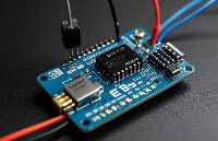
MFRC522是高度集成的非接觸式( 13.56MHz)讀寫卡芯片。此發送模塊利用調制和解調的原理,并將它們完全集成到各種非接觸式通信方法和協議中(13.56MHz)。
MFRC522的內部發送器部分可驅動讀寫器天線與ISO 14443A/MIFARE卡和應答機的通信,無需其它的電路。接收器部分提供一個功能強大和高效的解調和譯碼電路,用來處理兼容ISO 14443A/MIFARE的卡和應答機的信號。通信距離可達50mm,取決于天線的長度和調諧。數字電路部分處理完整的ISO 14443A幀和錯誤檢測(奇偶&CRC)。
- 支持MIFARE標準器件,如S50、S70,UID卡,
- 支持MIFARE Classic加密。
- 支持MIFARE更高速的非接觸式通信,雙向數據傳輸速率高達424kbit/s。
- 內部64字節的發送和接收FIFO緩沖區。
- 10Mbit/s的SPI接口
- I2C接口,快速模式的速率為400kbit/s,高速模式的速率為3400kbit/s
- 串行UART,傳輸速率高達1228.8kbit/s, 幀取決于RS232接口,電壓電平取決于提供的管腳電壓
本文將介紹ESP32開發板驅動MFRC522 RFID模塊,讀取RFID卡原始數據、獲取RFID卡的UID,并將個人數據添加到RFID卡中。
ESP32開發板與MFRC522模塊接線
下圖為SPI通信接線圖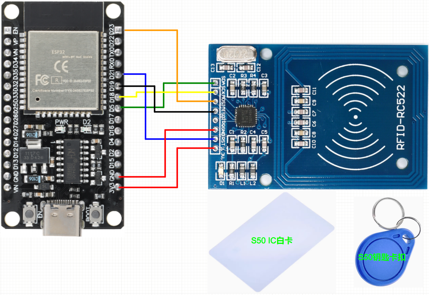
| ESP32 | MFRC522 |
|---|---|
| GPIO5 | SDA引腳作為SPI通信時的CS片選 |
| GPIO18 | SCK |
| GPIO23 | MOSI |
| GPIO19 | MISO |
| 不接 | IRQ |
| GND | GND |
| GPIO21 | RST |
| 3V3 | 3.3V |
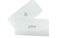
讀取S50 IC白卡與S50 IC鑰匙卡扣原始數據
Arduino IDE中安裝RFID_MFRCC522驅動庫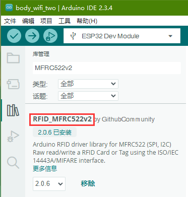
#include < MFRC522v2.h >
#include < MFRC522DriverSPI.h >
//#include < MFRC522DriverI2C.h >
#include < MFRC522DriverPinSimple.h >
#include < MFRC522Debug.h >

// Learn more about using SPI/I2C or check the pin assigment for your board: https://github.com/OSSLibraries/Arduino_MFRC522v2#pin-layout
MFRC522DriverPinSimple ss_pin(5);

MFRC522DriverSPI driver{ss_pin}; // Create SPI driver
//MFRC522DriverI2C driver{};     // Create I2C driver
MFRC522 mfrc522{driver};         // Create MFRC522 instance

void setup() {
  Serial.begin(115200);  // Initialize serial communication
  while (!Serial);       // Do nothing if no serial port is opened (added for Arduinos based on ATMEGA32U4).

  mfrc522.PCD_Init();    // Init MFRC522 board.
  MFRC522Debug::PCD_DumpVersionToSerial(mfrc522, Serial);	// Show details of PCD - MFRC522 Card Reader details.
  Serial.println(F("Scan PICC to see UID, SAK, type, and data blocks..."));
}

void loop() {
  // Reset the loop if no new card present on the sensor/reader. This saves the entire process when idle.
  if (!mfrc522.PICC_IsNewCardPresent()) {
    return;
  }

  // Select one of the cards.
  if (!mfrc522.PICC_ReadCardSerial()) {
    return;
  }

  // Dump debug info about the card; PICC_HaltA() is automatically called.
  MFRC522Debug::PICC_DumpToSerial(mfrc522, Serial, &(mfrc522.uid));

  delay(2000);
}
程序中PICC表示IC卡(proximity integrated circuit cards)
PCD表示讀寫模塊MFRC522(proximity coupling device)
編譯上傳程序到ESP32開發板 ,打開串口打印,把IC卡靠近MFRC522讀寫模塊,可在串口上打印出IC內存儲的數據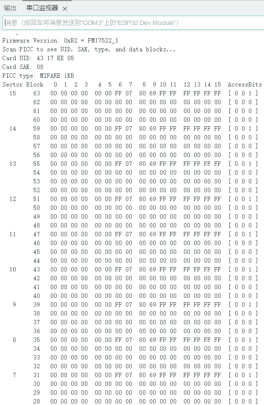
從串口打印出的信息可知道
IC卡的存儲分布結構劃分為16個(0-15)扇區,每個扇區包含4個(0-3)存儲塊,每個存儲塊包含16個字節的存儲(0-15)
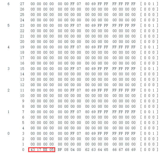
扇區0上的存儲塊0存儲著IC卡的出廠信息,第0-4字節為UUID(如43 17 EE 05),一個校驗字節,剩余的為出廠寫入的數據。存儲塊0為只讀模式,一般不可更改(部分克隆卡可修改)。
每個扇區的前3個存儲塊可用于存儲數據,每個扇區的最后一個存儲塊為扇區尾塊Sector Trailer。
每個扇區尾塊固定為 16字節,其數據結構如下:
0~5 Key A(6字節),扇區的第一個訪問密鑰(默認通常為 FF FF FF FF FF FF 或廠商預設值)。
6~8 Access Bits(4字節),存儲該扇區的訪問權限控制位(實際只用了3字節,第9字節為備用)。
10~15 Key B(6字節),扇區的第二個訪問密鑰(可選,部分應用可能不用或與Key A相同)。
每個扇區的最后一個塊是安全核心,決定了該扇區的訪問規則。操作時務必謹慎,建議先讀取并備份原始數據(需密鑰驗證),再嘗試修改。
IC卡的類型為MIFARE 1KB 用戶可用的凈存儲容量為:
16扇區 X 3存儲塊 X 16字節 - 16字節=752字節
UID為 43 17 EE 05 不同的卡的UID會不一樣
讀寫用戶數據到指定的存儲塊
#include < MFRC522v2.h >
#include < MFRC522DriverSPI.h >
//#include < MFRC522DriverI2C.h >
#include < MFRC522DriverPinSimple.h >
#include < MFRC522Debug.h >

// Learn more about using SPI/I2C or check the pin assigment for your board: https://github.com/OSSLibraries/Arduino_MFRC522v2#pin-layout
MFRC522DriverPinSimple ss_pin(5);

MFRC522DriverSPI driver{ss_pin}; // Create SPI driver
//MFRC522DriverI2C driver{};     // Create I2C driver
MFRC522 mfrc522{driver};         // Create MFRC522 instance

MFRC522::MIFARE_Key key;

byte blockAddress = 2;
byte newBlockData[17] = {"www.yourcee.com"};
//byte newBlockData[16] = {0,0,0,0,0,0,0,0,0,0,0,0,0,0,0,0};   // CLEAR DATA
byte bufferblocksize = 18;
byte blockDataRead[18];

void setup() {
  Serial.begin(115200);  // Initialize serial communication
  while (!Serial);       // Do nothing if no serial port is opened (added for Arduinos based on ATMEGA32U4).

  mfrc522.PCD_Init();    // Init MFRC522 board.
  Serial.println(F("Warning: this example overwrites a block in your card, use with care!"));

  // Prepare key - all keys are set to FFFFFFFFFFFF at chip delivery from the factory.
  for (byte i = 0; i < 6; i++) {
    key.keyByte[i] = 0xFF;
  }
}

void loop() {
  // Check if a new card is present
  if (!mfrc522.PICC_IsNewCardPresent() || !mfrc522.PICC_ReadCardSerial()) {
    delay(500);
    return;
  }

  // Display card UID
  Serial.print("----------------nCard UID: ");
  MFRC522Debug::PrintUID(Serial, (mfrc522.uid));
  Serial.println();

  // Authenticate the specified block using KEY_A = 0x60
  if (mfrc522.PCD_Authenticate(0x60, blockAddress, &key, &(mfrc522.uid)) != 0) {
    Serial.println("Authentication failed.");
    return;
  }

  // Write data to the specified block
  if (mfrc522.MIFARE_Write(blockAddress, newBlockData, 16) != 0) {
    Serial.println("Write failed.");
  } else {
    Serial.print("Data written successfully in block: ");
    Serial.println(blockAddress);
  }

  // Authenticate the specified block using KEY_A = 0x60
  if (mfrc522.PCD_Authenticate(0x60, blockAddress, &key, &(mfrc522.uid)) != 0) {
    Serial.println("Authentication failed.");
    return;
  }

  // Read data from the specified block
  if (mfrc522.MIFARE_Read(blockAddress, blockDataRead, &bufferblocksize) != 0) {
    Serial.println("Read failed.");
  } else {
    Serial.println("Read successfully!");
    Serial.print("Data in block ");
    Serial.print(blockAddress);
    Serial.print(": ");
    for (byte i = 0; i < 16; i++) {
      Serial.print((char)blockDataRead[i]);  // Print as character
    }
    Serial.println();
  }

  // Halt communication with the card
  mfrc522.PICC_HaltA();
  mfrc522.PCD_StopCrypto1();

  delay(2000);  // Delay for readability
}
byte blockAddress = 2;
定義了一個名為blockAddress的變量。這個變量指定了IC卡內將要寫入或讀取數據的塊。blockAddress被設置為2,將與卡片內存的第2個塊進行交互。如果你想寫入不同的塊,你可以更改這個值。
byte newBlockData[17] = {"www.yourcee.com"};
保存您想要寫入卡中的數據,不超過16個字節
byte newBlockData[16] = {0,0,0,0,0,0,0,0,0,0,0,0,0,0,0,0};
如果您想清除塊數據,取消注釋這行代碼
for (byte i = 0; i < 6; i++) {
key.keyByte[i] = 0xFF;
}
IC卡的默認密鑰也在以上行中設置。默認情況下,工廠密鑰的所有字節都是0xFF。這個密鑰允許訪問卡的數據塊。
if (mfrc522.PCD_Authenticate(0x60, blockAddress, &key, &(mfrc522.uid)) != 0) {
Serial.println("Authentication failed.");
return;
}
代碼嘗試使用默認密鑰(在本例中為塊2)對卡片上的特定塊進行認證。0x60是一個指定使用KEY_A進行認證的命令。KEY_A是RFID卡上可用的兩個密鑰(KEY_A和KEY_B)之一,每個密鑰提供不同的權限。使用0x60意味著代碼正在嘗試用KEY_A進行認證,而默認情況下,在MIFARE RFID卡上KEY_A是0xFF 0xFF 0xFF 0xFF 0xFF。
編譯上傳程序到ESP32開發板 ,打開串口監視器,并把IC卡 靠近MFRC522讀寫模塊,串口顯示出寫入并讀取到指定存儲塊的數據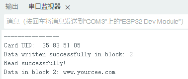
總結
本實驗只是對空白的MIFARE Classic IC卡進行簡單的讀寫驗證,由于IC卡大都有秘鑰,至于破解IC卡,復制C卡需要大家進一步探索研究了。
審核編輯 黃宇
-
RFID
+關注
關注
391文章
6440瀏覽量
242415 -
MFRC522
+關注
關注
2文章
30瀏覽量
17786 -
ESP32
+關注
關注
21文章
1017瀏覽量
19243
發布評論請先 登錄
別再用鑰匙啦!樹莓派Pico教你用RFID“刷”門禁~

RFID紙質芯片卡的應用
用于LEGIC Advant UID/序列號的NFC讀卡器,為什么無法讀取這些卡的UID/序列號?
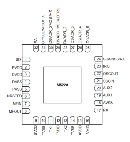
SI522A 低功耗尋卡與多款13.56MHZ 兼容開發資料
SI522這款13.56MHz芯片能兼容這么多款同行芯片
原來ESP32竟可《一“芯”兩用》既做人體檢測傳感器也做Wi-Fi數據傳輸

Si522A:高度集成的13.56MHz非接觸式讀寫器芯片數據手冊
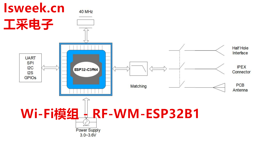
基于ESP32-C3FN4為核心自主研發的Wi-Fi+BT模塊-RF-WM-ESP32B1
SI522A 與 恩智浦 RC522 刷卡對比
esp8266和esp32區別是什么
esp32用什么軟件編程
如何讀取多張卡的UID,有償
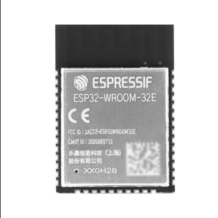
ESP32-WROOM-32E、ESP32-WROOM-32D、ESP32-WROOM-32U 有什么區別?ESP32-WROOM-32 后綴字母代表的意思是?


 工商網監
工商網監
評論