") 【產(chǎn)品應(yīng)用】AWorksLP 樣例詳解(MR6450)—— HWTimer
【產(chǎn)品應(yīng)用】AWorksLP 樣例詳解(MR6450)—— HWTimer
AWorksLP 對外設(shè)進(jìn)行了高度抽象化,為同一類外設(shè)提供了相同的接口,應(yīng)用程序可以輕松跨平臺。本文以MR6450平臺為例,介紹AWorksLP HWTimer 外設(shè)基本用法。 簡介在AWorksLP中將硬件定時器分為了4類,即延時型、計數(shù)型、周期型和輸入捕獲型硬件定時器。
- 延時型硬件定時器:
由硬件定時器外設(shè)提供的延時功能。
- 計數(shù)型硬件定時器:
提供較精確的類似時間戳的功能。
- 周期型硬件定時器:
可設(shè)置中斷頻率的計數(shù)器,不僅能提供計數(shù)器的功能,也能根據(jù)中斷頻率提供更精確的定時。
- 輸入捕獲定時器:可測量脈沖寬度或者測量頻率。
接口介紹延時型硬件定時器:
函數(shù)原型 | 簡要描述 |
aw_err_t aw_hwtimer_delay (int fd, struct aw_timespec *p_tv); | 延時 |
aw_err_t aw_hwtimer_delay_cancel (int fd); | 取消延時 |
計數(shù)型硬件定時器:
函數(shù)原型 | 簡要描述 |
aw_err_t aw_hwtimer_count_start (int fd); | 啟動一個計數(shù)型硬件定時器 |
aw_err_t aw_hwtimer_count_stop (int fd); | 停止一個計數(shù)型硬件定時器 |
aw_err_t aw_hwtimer_count_get (int fd, uint64_t *p_count); | 讀取計數(shù)值 |
aw_err_t aw_hwtimer_count_rate_get (int fd, uint32_t *p_rate); | 獲取計數(shù)時鐘頻率 |
aw_err_t aw_hwtimer_count_rate_set (int fd, uint32_t rate); | 設(shè)置計數(shù)時鐘頻率 |
aw_err_t aw_hwtimer_count_rate_set_accurate (int fd, uint32_t rate_numerator, uint32_t rate_denominator); | 以精確化的方式設(shè)置計數(shù)時鐘頻率 |
aw_err_t aw_hwtimer_count_rate_get_accurate (int fd, uint32_t *p_rate_numerator, uint32_t *p_rate_denominator); | 獲取計數(shù)時鐘頻率的精確描述 |
周期型硬件定時器:
函數(shù)原型 | 簡要描述 |
aw_err_t aw_hwtimer_period_wait (int fd, uint32_t wait_ms); | 等待定時器周期中斷 |
aw_err_t aw_hwtimer_period_intr (int fd); | 打斷周期型定時器的等待操作 |
aw_err_t aw_hwtimer_period_start (int fd); | 啟動定時器 |
aw_err_t aw_hwtimer_period_stop (int fd); | 停止定時器 |
aw_err_t aw_hwtimer_period_count_get (int fd, uint64_t *p_count); | 讀取計數(shù)值 |
aw_err_t aw_hwtimer_period_count_freq_get (int fd, uint32_t *p_rate); | 獲取周期型定時器的硬件計數(shù)頻率(不是中斷頻率) |
aw_err_t aw_hwtimer_period_count_freq_get_frac (int fd, aw_hwtimer_rate_t *p_rate); | 以更精確的分?jǐn)?shù)形式獲取周期型定時器的硬件計數(shù)頻率(不是中斷頻率) |
aw_err_t aw_hwtimer_period_intr_freq_set (int fd, uint32_t intr_freq); | 設(shè)置中斷頻率 |
aw_err_t aw_hwtimer_period_intr_freq_get (int fd, uint32_t *p_intr_freq); | 獲取中斷頻率 |
aw_err_t aw_hwtimer_period_intr_freq_set_frac (int fd, aw_const aw_hwtimer_rate_t *p_intr_freq); | 設(shè)置中斷頻率(以更精確的分?jǐn)?shù)形式) |
aw_err_t aw_hwtimer_period_intr_freq_get_frac (int fd, aw_hwtimer_rate_t *p_intr_freq); | 獲取中斷頻率(以更精確的分?jǐn)?shù)形式) |
輸入捕獲型硬件定時器:
函數(shù)原型 | 簡要描述 |
aw_err_t aw_hwtimer_cap_start (int fd); | 啟動輸入捕獲型硬件定時器 |
aw_err_t aw_hwtimer_cap_stop (int fd); | 停止輸入捕獲型硬件定時器 |
aw_err_t aw_hwtimer_cap_read (int fd, uint64_t *p_cap_val, uint32_t timeout_ms); | 讀取一個捕獲到的事件的計數(shù)值 |
aw_err_t aw_hwtimer_cap_intr (int fd); | 打斷阻塞read讀操作 |
aw_err_t aw_hwtimer_cap_config_set (int fd, aw_const aw_hwtimer_cap_config_t *p_config); | 配置輸入捕獲型硬件定時器 |
aw_err_t aw_hwtimer_cap_config_get (int fd, aw_hwtimer_cap_config_t *p_config); | 獲取輸入捕獲型硬件定時器的配置 |
使用樣例AWorksLP SDK相關(guān)使用請參考《AWorksLP SDK快速入門(MR6450)——開箱體驗》一文,本文不在贅述。1. 周期型定時器{SDK}\demos\peripheral\hwtimer路徑下為硬件定時器例程,默認(rèn)運行的是demo_hwtimer.c 周期型定時器的代碼,例程關(guān)鍵代碼如下:
/** * \brief 硬件定時器中斷服務(wù)函數(shù)。 * \param[in] p_arg : 任務(wù)參數(shù) */static void mytimer_isr (void *p_arg){ aw_gpio_toggle((int)p_arg); aw_kprintf("enter isr \n\r");}
/** * \brief hwtimer 測試函數(shù) */aw_local void* __task_handle (void *arg){ int fd; aw_err_t ret; uint32_t count = 5; aw_hwtimer_rate_t p_intr_freq;
p_intr_freq.rate_denominator = 5; p_intr_freq.rate_numerator = 1;
fd = aw_open(CONFIG_DEMO_HWTIMER_PEROID_DEV_NAME, AW_O_RDWR, 0); if (fd < 0) { ? ? ? ?aw_kprintf("hwtimer open failed:%d \n\r", fd); ? ? ? ?while(1); ? ?}
ret = aw_hwtimer_period_intr_freq_set_frac(fd, &p_intr_freq); while (count) { aw_hwtimer_period_wait(fd, 500); mytimer_isr(arg); count --; }
// 配置每秒中斷2次 ret = aw_hwtimer_period_intr_freq_set(fd, 2);
ret = aw_hwtimer_period_start(fd); if (ret != AW_OK) { aw_kprintf("Timer allocation fail!\n"); }
ret = aw_hwtimer_period_wait(fd, AW_WAIT_FOREVER);
while (1) { aw_hwtimer_period_wait(fd, AW_WAIT_FOREVER); mytimer_isr(arg); }
for (;;) { aw_mdelay(1000); } aw_close(fd);
return 0;}
在代碼中先使用了aw_hwtimer_period_intr_freq_set_frac 接口,以分?jǐn)?shù)的形式設(shè)置中斷頻率,使用aw_hwtimer_period_start接口啟動定時器。在循環(huán)中使用aw_hwtimer_period_wait 接口阻塞等待中斷的產(chǎn)生、中斷產(chǎn)生后繼續(xù)執(zhí)行mytimer_isr函數(shù)使LED 燈狀態(tài)翻轉(zhuǎn),由于設(shè)置的頻率為五分之一,所以5秒LED 燈的狀態(tài)翻轉(zhuǎn)一次;循環(huán)一定次數(shù)后用aw_hwtimer_period_intr_freq_set 接口設(shè)置中斷頻率為2HZ,循環(huán)等待中斷、翻轉(zhuǎn)LED。實驗現(xiàn)象為LED燈先以5s的頻率閃爍,同時串口打印同時信息。閃爍一定次數(shù)后以0.5s的頻率LED閃爍,同時串口打印信息。
下表為使用硬件周期型定時器,在中斷中進(jìn)行引腳翻轉(zhuǎn),通過邏輯分析儀所測量出的實際數(shù)據(jù),在使用設(shè)計時可作為部分參考依據(jù)。
定時時間(s) | 實際時間(s) |
0.010000000 | 0.010000115 |
0.020000000 | 0.019999940 |
0.030000000 | 0.029999980 |
0.040000000 | 0.040000035 |
0.050000000 | 0.049999830 |
0.100000000 | 0.100000075 |
0.200000000 | 0.200000020 |
0.500000000 | 0.500000070 |
1.000000000 | 1.000000760 |
2.000000000 | 1.999999340 |
3.000000000 | 3.000002760 |
4.000000000 | 4.000001980 |
5.000000000 | 5.000004310 |
10.000000000 | 10.000008300 |
2.計數(shù)型定時器在config配置腳本中選擇hwtimer count計數(shù)型定時器測試如圖1所示。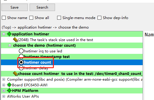 圖1 計數(shù)型定時器例程保存后重新Build工程,編譯好后運行的是demo_hwtimer_count.c的代碼,例程關(guān)鍵代碼如下:
aw_local void* __task_handle (void *arg){ uint32_t count = 0; int fd, led_fd; int ret; uint32_t start_count; fd = aw_open(CONFIG_DEMO_HWTIMER_PEROID_DEV_NAME, AW_O_RDWR, 0); if (fd < 0) { aw_kprintf("hwtimer open fail! :%d\n",fd); return; } /* 打開設(shè)備會點亮LED */ led_fd = aw_open("/dev/led_run", AW_O_RDWR, 0); if (led_fd < 0) { aw_kprintf("led open fail! :%d\n", led_fd); aw_close(fd); return; } ret = aw_hwtimer_count_rate_get(fd, &start_count); if (ret != AW_OK) { aw_kprintf("Timer count rate get fail!\n"); aw_close(fd); aw_close(led_fd); return; } // 設(shè)置時鐘頻率 ret = aw_hwtimer_count_rate_set(fd, start_count/2); if (ret != AW_OK) { aw_kprintf("Timer count rate set fail!\n"); aw_close(fd); aw_close(led_fd); return; } ret = aw_hwtimer_count_start(fd); if (ret != AW_OK) { aw_kprintf("Timer start fail!\n"); aw_close(fd); aw_close(led_fd); return; } for (;;) { aw_led_toggle(led_fd); aw_mdelay(500); aw_led_toggle(led_fd); aw_hwtimer_count_get(fd, &count); aw_kprintf("Count is %d\r\n", count); } aw_close(fd); aw_close(led_fd); return 0;}
在上述代碼中使用了aw_hwtimer_count_rate_get接口獲取改定時器時鐘頻率,可以在調(diào)試模式下查看獲取到的參數(shù),為100M 如圖2所示。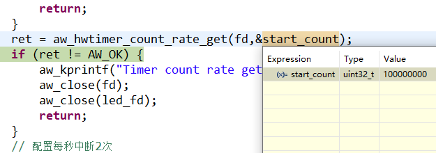 圖2查看參數(shù)使用aw_hwtimer_count_rate_set接口設(shè)置定時器時鐘的頻率為50M,使用aw_hwtimer_count_start接口開啟定時器,使用aw_hwtimer_count_get接口在循環(huán)中每延時500ms獲取一次計數(shù)值,并在串口中打印,打印結(jié)果如圖3所示。
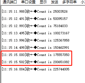
圖3串口打印計數(shù)值打印出的計數(shù)值中,相鄰兩個計數(shù)值之差為25M,是由于設(shè)置定時器頻率為50M,每延時500ms計數(shù)值增加25M。3.延時型定時器在config配置腳本中選擇hwtimer delay延時型定時器測試如圖4所示。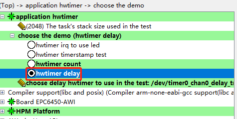 圖4計數(shù)型定時器例程保存后重新Build工程,編譯好后運行的是demo_hwtimer_count.c的代碼,例程關(guān)鍵代碼如下:
aw_local void* __task_handle (void *arg){ int i; int fd; aw_err_t ret; aw_timespec_t timespec; aw_timestamp_t start_timestamp, stop_timestamp; aw_timestamp_freq_t timestamp_freq; uint64_t delay_ns, diff; uint32_t ns_numerator = 1000000000;
timestamp_freq = aw_timestamp_freq_get(); while (0 == (timestamp_freq % 10)) { timestamp_freq /= 10; ns_numerator /= 10;}
fd = aw_open(CONFIG_DEMO_HWTIMER_DELAY_DEV_NAME, AW_O_RDWR, 0); if (fd < 0) { aw_kprintf("hwtimer open failed:%d \n\r", fd); while(1); }
delay_ns = 2001000; for (i = 0; i < 100; i++) { timespec.tv_sec = delay_ns / 1000000000u; timespec.tv_nsec = (uint32_t)(delay_ns % 1000000000u);
start_timestamp = aw_timestamp_get(); ret = aw_hwtimer_delay(fd, ×pec); if (ret !=AW_OK) { aw_kprintf("hwtimer delay failed:%d \n\r", ret); } aw_barrier(); stop_timestamp = aw_timestamp_get();
stop_timestamp -= start_timestamp; diff = stop_timestamp; diff *= ns_numerator; diff /= timestamp_freq;
diff = diff - delay_ns; aw_kprintf( "hwtimer_delay delay = %u,diff = %u ns\n", (uint32_t)delay_ns, (uint32_t)diff); delay_ns += 100000; } aw_close(fd); return 0;}
上述代碼中在延時開始前使用aw_timestamp_get接口記錄時間戳,使用aw_hwtimer_delay接口進(jìn)行延時,延時結(jié)束后記錄結(jié)束時間戳,用兩個時間戳的差值通過換算,用于對比延時不同時間下與timestamp相比的誤差,并在串口中打印,打印后增加延時時間,再次循環(huán),串口打印結(jié)果如下圖所示。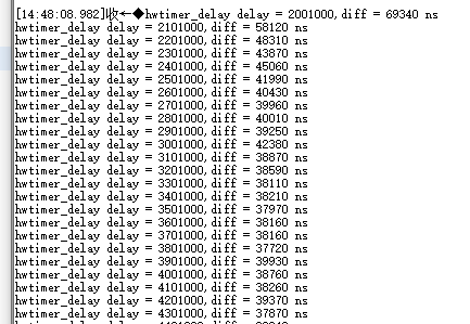 圖5串口打印結(jié)果因外設(shè)接口調(diào)用時代碼執(zhí)行需要時間以及晶振等硬件會導(dǎo)致誤差,分析例程打印數(shù)據(jù)可得,延時性定時器的軟件開銷在同一硬件以及接口下,其誤差基本是一致的。4. 捕獲型定時器
{SDK}\demos\peripheral\cap路徑下為捕獲型定時器例程,例程關(guān)鍵代碼如下:
/* 單邊沿觸發(fā)*/static void test_cap_single_edge( int fd, int gpio_cap, uint32_t ms, aw_hwtimer_cap_config_t *p_config, int is_rising){ uint64_t cap_val1, cap_val2; aw_err_t ret;
// 制造兩次上升沿 mk_edge(gpio_cap, 5); aw_task_delay(ms); mk_edge(gpio_cap, 5);
// 此時應(yīng)該產(chǎn)生了兩次捕獲事件 // 把它們讀出來 ret = aw_hwtimer_cap_read(fd, &cap_val1, AW_WAIT_FOREVER); if (AW_OK != ret) { aw_kprintf("cap read cap_val1 failed \n"); return; } ret = aw_hwtimer_cap_read(fd, &cap_val2, AW_WAIT_FOREVER); if (AW_OK != ret) { aw_kprintf("cap read cap_val2 failed \n"); return; }
cap_val2 -= cap_val1; cap_val2 *= 1000000; cap_val2 /= p_config->sample_rate;
if (is_rising) { aw_kprintf("two rising edge between %u ms \n", ms + 5); } else { aw_kprintf("two falling edge between %u ms \n", ms + 5); } aw_kprintf("two capture events between %llu us \n", cap_val2);}
static void demo_cap_base(int gpio_cap){ int fd; aw_err_t ret; aw_hwtimer_cap_config_t config;
// 使得測試GPIO輸出為0 aw_gpio_set(gpio_cap, 0);
fd = aw_open(CONFIG_DEMO_HWTIMER_CAP_DEV_NAME, AW_O_RDWR, 0); if (fd < 0) { aw_kprintf("cap open failed!\n"); return; }
// 獲取捕獲定時器的配置 ret = aw_hwtimer_cap_config_get(fd, &config); if (ret != AW_OK) { aw_kprintf("cap config get failed...\r\n"); aw_close(fd); return ; }
#if CONFIG_SINGLE_EDGE int is_rising; // 配置為上升沿觸發(fā)捕獲 config.cap_edge_flags = AW_CAPTURE_RISING_EDGE; is_rising = 1; ret = aw_hwtimer_cap_config_set(fd, &config); if (ret != AW_OK) { aw_kprintf("cap config set failed...\r\n"); aw_close(fd); return ; }
ret = aw_hwtimer_cap_start(fd); if (ret != AW_OK) { aw_kprintf("cap start failed...\r\n"); aw_close(fd); return ; } test_cap_single_edge(fd, gpio_cap, 20, &config, is_rising);#endif
aw_close(fd);}
在CAP 例程中默認(rèn)使用的是timer5_chan0,這個通道對應(yīng)的引腳是PF08,可以通過查看工程下timer5_chan0對應(yīng)的.h文件得知所使用的引腳的編號為168,通過查看hpm_pin.h頭文件可知編號168對應(yīng)的引腳為PF08 如下圖所示。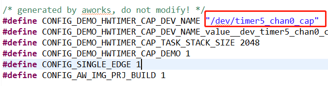 圖6默認(rèn)通道
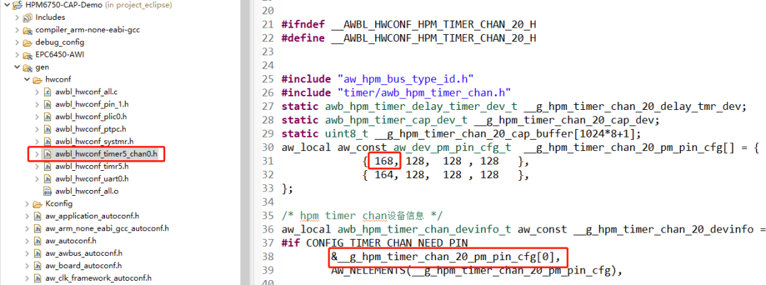 圖7對應(yīng)引腳編號
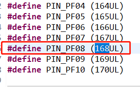
圖8對應(yīng)引腳本實驗中還用到了PF09 這個引腳,用于產(chǎn)生捕獲事件,PF09 和 PF08 這兩個引腳在開發(fā)板上并沒有引出來,不利于這次實驗,需要修改這兩個引腳。 圖9捕獲產(chǎn)生引腳參考{SDK} platforms\platform-hpm-aworks-lp\boards\EPC6450-AWI\dts 下的pins.dts 引腳描述文件,找到timer4_chan1 如圖10所示,timer4_chan1 使用的引腳是PE25, 對應(yīng)著開發(fā)板排針 UTX1 絲印的位置。
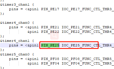 圖10捕獲產(chǎn)生引腳打開配置界面將timer5_chan0修改為timer4_chan1 如圖11所示,修改后點擊保存,重新build工程。
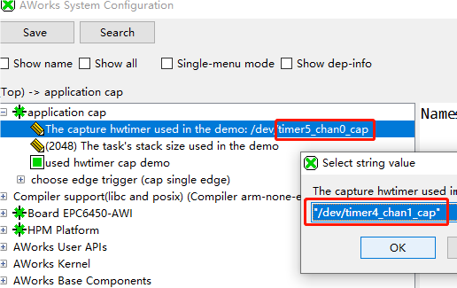 圖11配置界面將CAP_GPIO 對應(yīng)的引腳改為PIN_PE24,對應(yīng)著開發(fā)板排針 URX1 絲印的位置,如圖12所示。
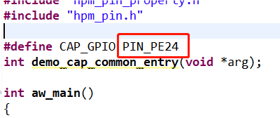
圖12CAP引腳將 PE25 , PE24 這兩個引腳,也就是排針上 URX1 和 UTX1 短接。
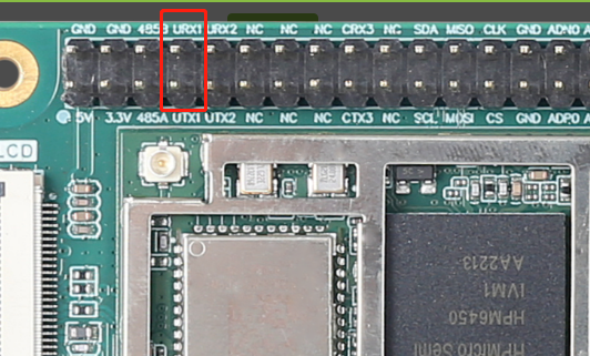
圖13引腳位置上訴代碼中使用aw_hwtimer_cap_config_get接口獲取捕獲定時器的配置信息,配置AW_CAPTURE_RISING_EDGE單通道模式后使用aw_hwtimer_cap_config_set接口配置捕獲定時器。使用aw_hwtimer_cap_start接口啟動定時器。在test_cap_single_edge函數(shù)中調(diào)用mk_edge函數(shù)制造兩次上升沿,使用aw_hwtimer_cap_read接口讀取這兩次事件捕獲到的計數(shù)值,計算出差值后在串口上顯示。在test_cap_single_edge函數(shù)中使用mk_edge函數(shù)中控制CAP_GPIO引腳輸出高電平后延時5ms再輸出低電平。延時20ms后再次調(diào)用mk_edge函數(shù),因此兩次上升沿事件間隔應(yīng)為25ms。串口打印結(jié)果如下圖所示。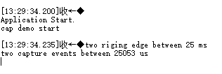 圖14串口打印結(jié)果
至此,所有類型的硬件定時器樣例均已展示完畢,在軟件應(yīng)用設(shè)計中可根據(jù)實際需求選取不同類型的定時器進(jìn)行使用。更多其他類型外設(shè)的用法介紹,請關(guān)注后續(xù)同系列推文~
-
接口
+關(guān)注
關(guān)注
33文章
8949瀏覽量
153218 -
定時器
+關(guān)注
關(guān)注
23文章
3288瀏覽量
117250
發(fā)布評論請先 登錄
基于瑞薩電子RA8T2 sensorless方案的樣例工程 可對電流環(huán)進(jìn)行TCM化設(shè)置
RISC-V生態(tài)崛起:政策落地與高性能芯片的崛起

深度解析 | 基于HPM6450的RISC-V核心板究竟有哪些過人之處?

40mR/650V SiC 碳化硅MOSFET,替代30mR 超結(jié)MOSFET或者20-30mR的GaN!
揚州航盛入選江蘇省重點領(lǐng)域首版次軟件產(chǎn)品應(yīng)用推廣指導(dǎo)目錄
關(guān)于cc2541程序代碼樣例
深蕾半導(dǎo)體開發(fā)者中心上線多個AI Demo樣例
vivo MR團(tuán)隊壯大,預(yù)計2025年上線高保真原型機(jī)
思必馳亮相2024全球人工智能產(chǎn)品應(yīng)用博覽會
為何ZLG致遠(yuǎn)電子要推出LGA嵌入式核心板?
差分硅振替換SiTime產(chǎn)品應(yīng)用于SSD,相位抖動低于350fs


 工商網(wǎng)監(jiān)
評論