") 怎樣用Wekinator和Arduino制作顏色分類器
怎樣用Wekinator和Arduino制作顏色分類器
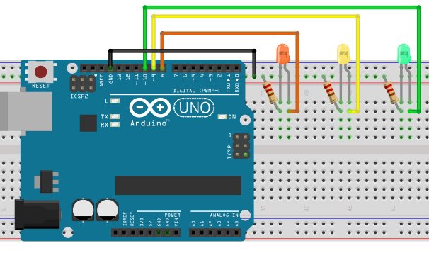
電路圖
如何運行程序
首先,在Arduino IDE的文章末尾粘貼為Arduino提供的代碼并上傳代碼。
然后您需要從Wekinator的示例頁面下載草圖。
下載源代碼以進行處理實現(xiàn)10x10顏色網(wǎng)格。解壓縮并在處理中運行代碼。該程序?qū)⑹褂霉P記本電腦的網(wǎng)絡(luò)攝像頭,根據(jù)您在攝像頭前所做的操作,它將為Wekinator提供輸入。
Wekinator的輸出需要另一個草圖。該草圖的代碼在本文末尾。將其粘貼到處理中并運行草圖。該草圖將從Wekinator輸出并將其發(fā)送到Arduino,LED將亮起。
兩個處理窗口應(yīng)如下所示。

現(xiàn)在打開Wekinator并進行如下圖所示的設(shè)置。將輸入設(shè)置為100,將輸出設(shè)置為1.將類型設(shè)置為3的所有分類器,然后單擊下一步。

在前面拿一張彩色紙攝像頭并開始錄制半秒。
現(xiàn)在將班級更改為2.再次,向網(wǎng)絡(luò)攝像頭顯示另一種顏色的紙張,開始錄制半秒鐘。
現(xiàn)在將類更改為3,顯示另一種顏色的紙張,然后開始錄制半秒鐘。
之后,單擊“Train”,然后單擊“Run”。現(xiàn)在連接到Arduino的LED將根據(jù)您在網(wǎng)絡(luò)攝像頭前顯示的顏色亮起。
ArduinoCode
#include //Including the library that will help us in receiving and sending the values from processing
ValueReceiver《1》 receiver; /*Creating the receiver that will receive only one value.
Put the number of values to synchronize in the brackets */
/* The below variable will be synchronized in the processing
and they should be same on both sides. */
int output;
// Initializing the pins for led‘s
int led1 = 8;
int led2 = 9;
int led3 = 10;
void setup()
{
/* Starting the serial communication because we are communicating with the
Arduino through serial. The baudrate should be same as on the processing side. */
Serial.begin(19200);
pinMode(led1, OUTPUT);
pinMode(led2, OUTPUT);
pinMode(led3, OUTPUT);
// Synchronizing the variable with the processing. The variables must be int type.
receiver.observe(output);
}
void loop()
{
// Receiving the output from the processing.
receiver.sync();
// Matching the received output to light up led’s
if (output == 1)
{
digitalWrite(led1, HIGH);
digitalWrite(led2, LOW);
digitalWrite(led3, LOW);
}
else if (output == 2)
{
digitalWrite(led1, LOW);
digitalWrite(led2, HIGH);
digitalWrite(led3, LOW);
}
else if (output == 3)
{
digitalWrite(led1, LOW);
digitalWrite(led2, LOW);
digitalWrite(led3, HIGH);
}
}
處理代碼
import vsync.*; // Importing the library that will help us in sending and receiving the values from the Arduino
import processing.serial.*; // Importing the serial library
// Below libraries will connect and send, receive the values from Wekinator
import oscP5.*;
import netP5.*;
// Creating the instances
OscP5 oscP5;
NetAddress dest;
ValueSender sender;
// This variable will be syncronized with the Arduino and it should be same on the Arduino side.
public int output;
void setup()
{
// Starting the serial communication, the baudrate and the com port should be same as on the Arduino side.
Serial serial = new Serial(this, “COM10”, 19200);
sender = new ValueSender(this, serial);
// Synchronizing the variable as on the Arduino side. The order should be same.
sender.observe(“output”);
// Starting the communication with Wekinator. listen on port 12000, return messages on port 6448
oscP5 = new OscP5(this, 12000);
dest = new NetAddress(“127.0.0.1”, 6448);
}
// Recieve OSC messages from Wekinator
void oscEvent(OscMessage theOscMessage) {
if (theOscMessage.checkAddrPattern(“/wek/outputs”) == true) {
// Receiving the output from Wekinator
float value = theOscMessage.get(0).floatValue();
// Converting the output to int type
output = int(value);
}
}
void draw()
{
// Nothing to be drawn for this example
}
-
Arduino
+關(guān)注
關(guān)注
188文章
6491瀏覽量
190103
發(fā)布評論請先 登錄
PCB顏色代表什么顏色?如何選擇PCB顏色?一文幫你快速搞定
如何用SS1系列顏色傳感器示教多通道顏色?

如何用SS1系列顏色傳感器設(shè)置目標(biāo)顏色?


 工商網(wǎng)監(jiān)
評論