 電子發燒友App


編輯
刪除
最近打算將自己在其它地方發過的一些帖子收集整理一下,算是留個備份,省得自己以后找一些資料也麻煩。這個帖子得原來位置在馬達控制應用筆記和參考代碼--看看這個帖的訪問量能達
真正的技術問題,在ST MCU論壇上還是太少了。不知道是用的人太少,還是ST推廣不夠……?(怎么覺得好像是罵在自己啊?首先申明我不是ST的)以前在其它網站上曾經有整理貼出來過,既然這里有人問道ST7MC系列,順手將這些資料轉來這里,部分內容稍有刪除。
最近發現突然出現很多人問起如何使用MCU來控制馬達,由于工作的原因,一直有在接觸ST7MC和dsPIC30F的BLDC變頻控制,手上到是有一些這樣的資料,分別是ST7MC系列、TI TMS320LF2xxx系列、Microchip PIC18和dsPIC系列、Freescale MC68H和MC56F800系列的馬達控制資料。里面有設計簡單的馬達控制應用,也有用了PI算法的,也有使用空間矢量算法的。我干脆分帖將這些資料列出來。大家一個方便,有需要的自己找自己所需吧。我本人使用過ST7MC、diPIC30F4011、TMS320LF2407、MC56F8156,不過只有ST7MC是現在用的最多的,后面的兩個型號很久以前讀書時畢業設計用來做UPS并機的,現在都差不多忘光了,只是還留下點資料,也一并整理出來給大家參考,免得需要的時候滿大街找,不知到哪有。資料我可不負責更新啊。
相信大家只要了解電機特性,明白控制理論,用什么單片機都應該是一樣的。資料都是英文的,請不要向我要中文的資料,如果我有中文的話,我會盡量提供。PDF格式為應用筆記,ZIP或RAR為參考代碼。適當的地方我會加一點中文概述,方便大家。
一、ST7MC部分
ST單片機首頁
這里你可以找到所有ST官方的單片機的資料,包括數據手冊、用戶手冊、應用筆記、參考代碼、開發環境
ST7MC的官方網頁頁面:
?fdir=pages&fnam=st7mc
ST7MC的官方應用筆記頁面:
?name=mcu&file=familiesdocs&FAM=30#Application%20Note
里面有提及ST92141的,這個型號ST已經不建議在新的設計中使用了,使用ST7MC來替代。
1、ST7MC Three-Phase AC Induction Motor Ccontrol Software Library
2、ST7MC Three-Phase BLDC Motor Control Software Library
這個庫使用的是三次諧波,PI算法實現電流環或電壓環的閉環控制。
3、ST7MC PMAC Sine Wave Motor Control Software Library
4、PFC for ST7MC Starter Kit
5、PWM Management for 3-Phase BLDC Motor Drives using the ST7FMC
6、Back EMF detection during PWM on time by ST7MC
7、Space Vector Modulation using 8-Bit ST7FMC Microcontroller and AK-ST7FMC Starter Kit
用ST7MC實現空間矢量算法,有詳細的思路說明,具體的參考代碼沒有找到
8、ST7MC1 ST7MC2 datasheet
9、BLDC Sensor Motor Stand Alone library rev 2.0
10、BLDC Sensorless Motor Stand Alone Library rev 2.1
11、ST7MC Three-phase AC Induction Motor Control Library Rev 2.0
12、ST7MC-KIT/BLDC Starter kit Software Suite.
(includes comprehensive PC Graphical User Interface and C Software libraries for standalone operation of the starter kit)
這個GUI可以看到調試的時候需要配置那些參數。
13、ST有一些內部培訓的材料,下列的資料僅用于技術交流,請勿用于商業用途。如需商業用途,請刪除下述這些資料,然后自行與ST聯系獲取你的需要。希望下載者注意!
AC Induction Motor
AC Induction Motor
1)、AC Induction Motor Advanced.pdf
2)、AC Induction Motor Basics.pdf
3)、AC Motor Control Library Overview.pdf
4)、Use of GUI and stand-alone software.pdf
5)、Working with the AC Motor Control Software Library.pdf
6)、Hands-on session exercises.pdf
7)、AC induction motor MTC peripheral exercise.pdf
8)、AC induction motor MTC peripheral,features and associated registers.pdf
9)、Sinewave generation technique.pdf
10)、Sinewave generation technique(Solution).pdf
BLDC Motor
1)、BLDC Motor basics.pdf
2)、ST7FMC2x BLDC Motor Peripheral.pdf
3)、ST7FMC2x Microcontroller.pdf
4)、BLDC START & DRIVE.pdf
5)、BLDC Flowchart.pdf
6)、Starter Kit & GUI.pdf
7)、BLDC MOTOR BASIC.pdf
8)、BLDC motor MTC peripheral exercise.pdf
14、ST7 Flash STICK User Manual
ST7-STICK manufacturing files
這是ST7 Stick的PCB gerber和電路原理圖文檔。這個工具是ST7的并口版編程器,支持目前大多數的ST7系列MCU編程。如果你手上有ST7MC,只要有快這樣的板子,你就可以開始開發了。這是官方的資料,既然放出來了,應該是可以自己拿來做的。
15)、電機控制.pdf
電機控制的概念,工作原理,拓撲 L62xx系列設計參考資料、注意事項,如果需要使用ST的分立馬達驅動模塊,這是一份非常有用的資料。
二、Ti DSP TMS320LF2xxx部分
Application Software C2000 Apps Software from Texas Instruments
?sectionId=3&tabId=475&familyId=110&toolTypeId=32
里面有幾種常見的電機驅動參考代碼,DSP的,含F24系列、F28系列。
三、Microchip部分
四、Freescale部分
Freescale有一款DSP,和目前Microchip的dsPIC結構類似,也是MCU+DSP模式,他們是MC56F83xx/DSP56xxx系列。這一款DSP用于馬達驅動、變頻控制是一個不錯的選擇。建議大家看了資料以后,需要了解的只是看懂驅動的原理不要太過分沉迷與器件,比如對照C語言的源文件理解空間矢量。個人感覺其實用什么MCU或DSP驅動都是一樣,只要資源可以滿足要求都是可以使用的。Freescale的資料其實蠻多的,我這里只提供Reference Designs的列表,需要了解的只要下載Reference Manuals基本上就可以了解個大概。我僅列出與馬達控制、變頻驅動相關的資料列表(凡是有列出內容,但沒有詳細下載地址的可與我聯系[email protected],,也可以到Freescale的網站上注冊ID后再下載):
1、RD56F801XACIM
Design of an ACIM Vector Control Drive using the 56F801X
1)、Reference Manuals:
2、RD56F801XBLDCHS
3-Phase BLDC Motor Control with Hall Sensor Using 56F801X Digital Signal Controllers
1)、Users Guides:
2)、Application Notes
3)、Reports or Presentations
4)、Code Examples
Code Examples.zip
3、RD56F801XPMSMBLDC
PMSM and BLDC Sensorless Motor Control using the 56F801X
1)、Reference Manuals:
2)、Reports or Presentations
4、RD56F8300OUPS
Online UPS using a 56F83xx Device
1)、Reference Manuals:
2)、Schematics
OrCAD Schematic Capture design file for the 56F8300 UPS Control Board
OrCAD Schematic Capture design file for the 56F8300 UPS Power Board
5、RD56F8300SMPS
Digital AC/DC Switched-Mode Power Supply using a 56F8300 Digital Signal Controllers
1)、Reference Manuals:
2)、Application Notes
3)、Training Reference Material
6、RDDSCSENSORLESSBLDC
3-Phase Brushless DC Motor Sensorless Control using 56F801X
1)、Reference Manuals:
2)、Application Software
7、RDDSP56F8ACIMVHD
3-Phase ACIM Volt per Hertz Motor Control Using 56F80X or 56F8300 Digital Signal Controllers
1)、Reference Manuals:
8、RDDSP56F8ACVCD
3-Phase AC Induction Motor Vector Control Using 56F80X or 56F8300 Digital Signal Controllers
1)、Reference Manuals:
2)、Application Software
9、RDDSP56F8BLDCAZC
3-Phase BLDC Motor Control with Sensorless Back-EMF ADC Zero Crossing Detection Using 56F80X or 56F8300 Digital Signal Controllers
1)、Reference Manuals:
2)、Application Software
10、RDDSP56F8BLDCE
3-Phase BLDC Motor Control with Encoder using 56F80X or 56F8300 Digital Signal Controllers
1)、Application Notes :
11、RDDSP56F8BLDCHS
3-Phase BLDC Motor Control with Hall Sensor Using 56F80X or 56F8300 Digital Signal Controllers
1)、Reference Manuals:
2)、Application Software
12、RDDSP56F8BLDCZC
3-Phase Sensorless BLDC Motor Control with Back-EMF Zero Crossing Detection using 56F80X or 56F8300 Digital Signal Controllers
1)、Reference Manuals:
2)、Application Software
13、RDDSP56F8PMSDE
3-Phase PM Synchronous Motor Control with Quadrature Encoder Using 56F80X Digital Signal Controllers
1)、Reference Manuals:
2)、Application Software
14、RDDSP56F8SMTVC
3-Phase PM Synchronous Motor Torque Vector Control Using 56F80X or 56F8300 Digital Signal Controllers
1)、Reference Manuals:
2)、Application Software
Software Files for 3-Phase PM Synchronous Motor Torque Vector Control Using 56F805
Software Files for 3-Phase PM Synchronous Motor Torque Vector Control Using 56F8300
15、RDDSP56F8SRDE
3-Phase Switched Reluctance Motor Control with Encoder Using 56F80X Digital Signal Controllers
1)、Reference Manuals:
2)、Application Software
16、RDDSP56F8SRDHS
3-Phase SR Motor Control with Hall Sensor Reference Design for 56F80X or 56F8300 Digital Signal Controllers
1)、Reference Manuals:
2)、Application Software
17、RDDSP56F8SRDS
3-Phase SR Motor Sensorless Control Reference Design using 56F80X or 56F8300 Digital Signal Controllers
1)、Reference Manuals:
2)、Application Software
五、Atmel AT90PWMx
就是資料太少,看上起在低成本的競爭上性能與配置蠻有優勢的,就是不知道價格如何?
AT90PWM2/3 DataSheet
Code example for AT90PWM3 - PSC1 in 1 ramp mode Code example in C language for IAR compiler
Code example for AT90PWM3 - PSC1 in 1 ramp mode Code example in Assembly language for AVR Studio
Code example for AT90PWM3 - PSC1 in 2 ramps mode Code example in C language for IAR compiler
Code example for AT90PWM3 - PSC1 in 4 ramps mode Code example in C language for IAR compiler
Code example for AT90PWM3 - PSC1 in centered aligned ramp mode Code example in C language for IAR compiler
ATAVRMC100 - BLDC Motor Control Hardware User Guide
AVR440: Sensorless Control of Two-Phase Brushless DC Motor
AVR441: Intelligent BLDC Fan Controller with Temperature Sensor and Serial Interface
AVR442: BLDC Fan Motor Control with ATtiny13
AVR443: Sensor-based control of three phase Brushless DC motor
AVR444: Sensorless control of 3-phase brushless DC motors
AVR448: Control of High Voltage Three-phase BLDC Motor
AVR492: Brushless DC Motor control using AT90PWM3
AVR494: AC Induction Motor Control Using the constant V/f Principle and a Natural PWM Algorithm
AVR495: AC Induction Motor Control Using the Constant V/f Principle and a Space-vector PWM Algorithm
120度驅動BLDC和180度驅動BLDC的區別
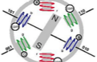
通常對于BLDC所說的6步法驅動:
下圖是一個簡單的BLDC馬達六步法的簡單示意圖:
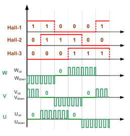
按照六步法的每個相的導通次序,我們可以得到每個開關的導通時序:
如果把它的每一相的電壓的導通時間以導通角度來做橫坐標,我們可以看到:
1、每一相的導通角度是120度;
2、在每一相的導通時間內是使用PWM信號來調制的;
有傳感器(霍爾)和無傳感器(反電動勢BEMF)是兩種不同的 轉子位置反饋方式。檢測到轉子的位置目的是為了實現換相。
在第二幅圖中我們可以看到:
當BEMF到通過PhaseA、PhaseB、PhaseC中間值(即1/2VCC)時,可以算出轉子的位置。
那BEMF又是如何實現?
上圖的mx 點即為反電動勢過零點,其中 x=1,2,3,4,5,6。對于特定的某一相而言,以 a 相為例, (x=3, 6)所處的60° 扇區即為反電動勢過零檢測區域。上圖橫坐標所對應的電壓為半電壓uN。
這樣我們可以知道:
1. 反電動勢過零點超前于實際換相點30°
2. 一個電周期內,任一相反電動勢有兩次過零
3. 檢測反電動勢過零點等效于檢測實際換相點(霍爾位置傳感器)
4. 反電動勢檢測可以簡化為反電動勢過零檢測
這里需要注意的是:反電動勢過零檢測只是針對任意時刻沒有通電的線圈(相/繞組)而言。
下面這份圖時Freescale給出的一個相壓和BEMF的關聯圖:
對于BEMF牟裳屑鋼址椒ǎ車氖鞘褂?個電阻虛擬一個中性點,即虛地:
在PWM導通期間, 中點的電壓位HV/2。這樣通過三個電阻與每個相線連接,然后連在一起,人為的創建一個虛地點。
ST7MC使用了另一種方式:
這樣做的好處?看上面的兩種圖啊。
120度和180度的區別在與其推動每一相的導通角不一樣。
1、每一相的導通角為180;
2、輸出的信號為正弦波;
對電流分解有激勵電流(D軸)和轉矩電流(Q軸)
1、D軸:一般為永磁體磁場方向;
2、Q軸:電樞電流方向,滯后D軸90度;
此類驅動一般都是用矢量控制的方式。下圖是TI的一份應用筆記中給出的控制函數模型:
下圖是瑞薩給出的一個數學原型:
對于180的驅動我也不是很懂,只是了解了一點皮毛,仍在琢磨中。
上述給出的貼圖多是來自ST的ST7MC、Freescale、Ti、Microchip的DSP應用筆記,要是對馬達驅動有興趣,可以去這些網站上看看。


 工商網監
工商網監
評論