 剎車燈(英文),Pulsing Third Brake Light
剎車燈(英文),Pulsing Third Brake Light
關鍵字:剎車燈(英文)
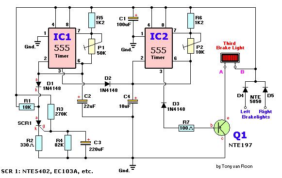
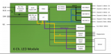
Circuit dijagram
Parts
IC1,IC2 = 555 Timer, RS #276-1723
SCR1 = NTE/ECG5402, RS #276-1067, EC103A, MCR104, etc.
Q1 = NTE/ECG197, SK3083, TIP125, or equivalent
D1,D2,D3 = 1N4148, 1N914, NTE/ECG519, RS #276-1122
D4,D5 = 1N5400, NTE/ECG5850, RS #276-1141, or equivalent
R1 = 18K
R2 = 330 ohm (RS #271-1315)
R3 = 270K
R4 = 82K
R5,R6 = 1K2
R8 = 100 ohm (RS# 271-1311)
P1 = 50K, 10-turn
P2 = 10K, 10-turn
C1 = 100?μF/16V (RS# 272-1016)
C2 = 22?μF/16V (RS# 272-1014)
C3 = 220?μF/16V (RS# 272-1017)
C4 = 10?μF/16V (RS# 272-1013)
Q1 is a PNP Silicon Audio Power Out/Medium Power Switch Transistor, 7A, with a TO-220 case. As long as you have a transistor which is close it will work fine. The SCR is a 100vrm, 0.8A, sensitive gate with a TO-92 case. Diodes D1, D2 and D3 are standard small signal diodes. Power diodes D4 and D5 are the 6A, 50prv types, cathode case. The 60vrm type will work as well. I used for IC1 & IC2 the LM555 type. P1 controls the 'on' and pulse-duration, P2 controls the pulse-timing.
Applying the Brakes:
When you first press the brakes, this circuit will turn on your 3rd brake light via the main brake lights. After about a second a series of short strobe pulses occur. The number of pulses range from approximately 1 to 10, depending on the setting of P1/P2 and when the brake pedal was applied last. After the pulses have been applied the third brake light assumes normal operation. The prototype was set for five flashes which seemed more than enough. Two days later I re-adjusted the trimmer potentiometers for 4 flashes--1/2 second pause--4 flashes. Looks pretty cool!
When you first press the brakes, this circuit will turn on your 3rd brake light via the main brake lights. After about a second a series of short strobe pulses occur. The number of pulses range from approximately 1 to 10, depending on the setting of P1/P2 and when the brake pedal was applied last. After the pulses have been applied the third brake light assumes normal operation. The prototype was set for five flashes which seemed more than enough. Two days later I re-adjusted the trimmer potentiometers for 4 flashes--1/2 second pause--4 flashes. Looks pretty cool!
Circuit Description:
The schematic consists of two 555 timer/oscillators in a dual timer configuration both setup in astable mode. When power is applied via the brake pedal, the brake light driver Q1 is switched on via the low-output pin 3 of IC2, and timer IC1 begins its timing cycle. With the output on pin 3 going high, inhibiting IC2's pin 2 (trigger) via D2, charge current begins to move through R3, R4 and C2.
When IC1's output goes low, the inhibiting bias on pin 2 of IC2 is removed and IC2 begins to oscillate, pulsing the third brake light via the emitter of Q1, at the rate determined by P2, R6, and C4. That oscillation continues until the gate-threshold voltage of SCR1 is reached, causing it to fire and pull IC1's trigger (pin 2) low. With its trigger low, IC1's ouput is forced high, disabling IC2's trigger. With triggering disabled, IC2's output switches to a low state, which makes Q1 conduct turning on the 3rd Brake Light until the brakes are released. Obviously, removing the power from the circuit at any time will reset the Silicon Controlled Rectifier SCR1, but the RC network consisting of R4 and C2 will not discharge immediately and will trigger SCR1 earlier. So, frequent brake use means fewer flashes or no flashes at all. But I think that's okay. You already have the attention from the driver behind you when you used your brakes seconds before that.
The collector/emitter voltage drop accross Q1 together with the loss over the series fed diodes D4/D5, will reduce the maximum available light output, but if your car's electrical system is functioning normally in the 13 - 14volt range, these losses are not noticeable.
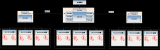
Building Tips:
You can easily build this circuit on perfboard or on one of RS/Tandy's experimentors boards (#276-150), or use the associated printed circuit board listed here.
Keep in mind that Q1 will draw most likely 2 or 3 amps and mounting this device on a heat sink is highly recommended. Verify that the scr is the 'sensitive gate' type. In incandecent bulbs, there is a time lag between the introduction of current and peak brightness. The lag is quite noticeable in an automotive bulb, so the duration of a squarewave driving such a bulb should be set long enough to permit full illumination. For that reason, and because lamps and car electrical systems vary, adjustment via P1 and P2 is necessary to provide the most effective pulse timing for your particular vehicle.
The reason that the third light is connected to both brake lights is to eliminate the possibility of a very confusing display when you use your turn signal with the brakes applied.
The cathode of D4 and D5 are tied together and go to point 'B' of the third brake light in the component layout diagram. Point 'A' goes to the other leg of the third brake light. Most if not all third brake lights in Canada & USA have two wires, the metal ones also have a ground wire which obviously goes to ground. I don't know the wiring schema for Australian and European third brake lights.
Don't forget the three jumpers on the pcb; two jumpers underneath IC1/IC2 between pin 4/8 and the one near Q1/R6.
If you use a metal case, don't forget to insulate the D4/D5 diodes.
Some 90's cars, like my 1992 Mercury Sable, have two bulbs inside the third brake light, each bulb is hooked up seperately to the left and right brake light for reasons only Ford knows. Click here for a possible 2-bulb hookup. It shows how I modified mine to get it working; and that was easier than I expected. Current draw with the two bulbs was measured at 1.85Amps (1850mA). Even with double the current none of the circuit components were getting hot. I had to re-adjust the two pots to make it flash since the bench testing was done with one bulb.
Bench Testing:
I tested different semiconductors like the 1N5401/1N5404, NTE153, and 4A type powerdiodes for D4/D5. All worked very well. As expected, Q1 is getting very hot. Current draw was measured between 680 - 735mA with a regular automotive 'headlight' bulb, extra heavy duty to make sure the circuit was safe. I tested several other power transistors including some darlingtons like the TIP125 and the TIP147. I eventually settled for the TIP125 myself because I had it available but any thing with 5A or more will do fine.
The actual third brake bulb is a lot smaller. Adjusting the trimpots (P1/P2) may take a bit of patience but really fine-tunes the circuit well. The only drawback of this circuit is the discharge lag coming from the electrolytic capacitor C2 and the R4 resistor. Especially if the brakes are used often or at short intervals the third brake light will not flash or maybe flash once or twice. Again, this is because the R-C combo does not have enough time to discharge in between braking. It takes about 12 seconds to discharge C2.
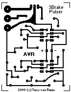
The pcb measures 2 x 2.5 inch (5 x 6.4cm or 170 x 200 pixels)
at 2 colors and is shown smaller when you print these pages.
If you need a direct, full size copy of the pcb I suggest to load the gif file into a program like Paint Shop Pro or one of the many gif viewers available.
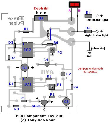
The layout is enlarged a bit for a better component view. Note that Q1 is drawn soldered on the pcb but if you have a metal case you can put it anywhere on the metal case (as a coolrib) and use havy duty wiring between Q1 and the PCB.
I tested different semiconductors like the 1N5401/1N5404, NTE153, and 4A type powerdiodes for D4/D5. All worked very well. As expected, Q1 is getting very hot. Current draw was measured between 680 - 735mA with a regular automotive 'headlight' bulb, extra heavy duty to make sure the circuit was safe. I tested several other power transistors including some darlingtons like the TIP125 and the TIP147. I eventually settled for the TIP125 myself because I had it available but any thing with 5A or more will do fine.
The actual third brake bulb is a lot smaller. Adjusting the trimpots (P1/P2) may take a bit of patience but really fine-tunes the circuit well. The only drawback of this circuit is the discharge lag coming from the electrolytic capacitor C2 and the R4 resistor. Especially if the brakes are used often or at short intervals the third brake light will not flash or maybe flash once or twice. Again, this is because the R-C combo does not have enough time to discharge in between braking. It takes about 12 seconds to discharge C2.
The pcb measures 2 x 2.5 inch (5 x 6.4cm or 170 x 200 pixels)
at 2 colors and is shown smaller when you print these pages.
If you need a direct, full size copy of the pcb I suggest to load the gif file into a program like Paint Shop Pro or one of the many gif viewers available.
The layout is enlarged a bit for a better component view. Note that Q1 is drawn soldered on the pcb but if you have a metal case you can put it anywhere on the metal case (as a coolrib) and use havy duty wiring between Q1 and the PCB.
CORRECTION: SCR1's anode/kathode
were shown reversed (fixed: 2-26-2000).
were shown reversed (fixed: 2-26-2000).
Author: Tony van Roon
聲明:本文內容及配圖由入駐作者撰寫或者入駐合作網站授權轉載。文章觀點僅代表作者本人,不代表電子發燒友網立場。文章及其配圖僅供工程師學習之用,如有內容侵權或者其他違規問題,請聯系本站處理。
舉報投訴
發布評論請先 登錄
相關推薦
熱點推薦
帝奧微24通道像素級尾燈高側驅動方案DIA82924介紹
在當今的汽車設計領域,汽車尾燈通常由剎車燈、倒車燈、轉向燈和霧燈等組成,是車輛與后方交通參與者溝通的重要橋梁。汽車尾燈不僅承擔著傳遞車輛行駛狀態與意圖、保障道路交通安全的核心使命,更在個性化與創新
車燈密封性試驗機:保障車燈品質的關鍵“衛士”
在汽車的許多部件中,雖然大燈很小,但它起著至關重要的作用。大燈密封試驗機是確保大燈質量的重要“檢查員”,在許多方面發揮著重要作用。(1)保證車燈的防水性能在駕駛過程中,汽車不可避免地會遇到各種惡劣
剎車步進電機的特點
剎車步進電機作為一種結合了步進電機精確控制與制動功能的特種電機,其獨特的設計和工作原理使其在需要快速啟停、精確定位的場景中展現出不可替代的優勢。以下從技術原理、性能特點、應用場景及發展趨勢等方面展開
華為亮相2025 ALE車燈展
2025年3月26日至3月28日,第20屆ALE車燈展在昆山花橋國際博覽中心盛大舉行,這場行業盛會匯聚全球頂尖主機廠、車燈企業以及上下游供應商,各方共同探討智能車燈的前沿技術、創新應用與未來發展趨勢。
鴻利智匯旗下誼善車燈邀您相約2025上海國際汽車燈具展
3月26-28日,鴻利智匯集團旗下子公司誼善車燈將參加2025上海國際汽車燈具展(ALE),展示多款創新LED車燈產品和汽車照明解決方案,誠邀您蒞臨展位B-T205,共探車燈技術發展新
汽車車燈檢測與可靠性驗證
汽車車燈檢測的重要性汽車車燈是車輛安全系統中不可或缺的關鍵組件,其性能與可靠性對行車安全有著至關重要的影響。車燈不僅要為駕駛者提供良好的照明,還要在各種復雜的環境條件下正常工作,以確保車輛的行駛安全
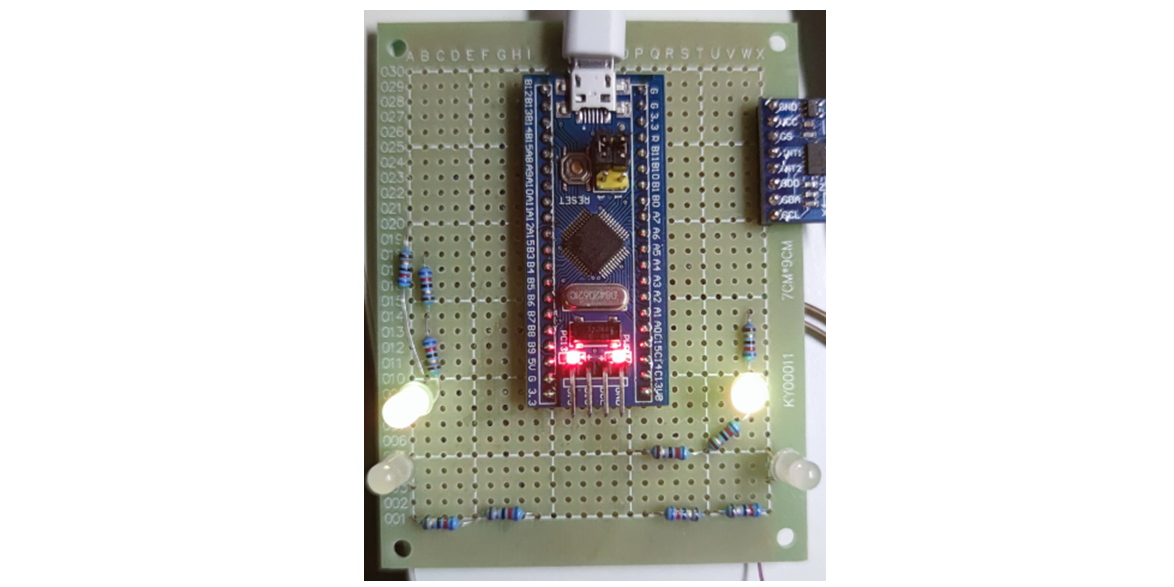
基于STM32設計的姿態感應剎車燈
本項目為自行車騎行者提供一種智能化的安全提示系統,采用ADXL345陀螺儀、STM32F103C8T6主控芯片及四枚LED燈,通過實時監測自行車的加速度變化,實現自動剎車燈功能。
汽車制動系統如何提升剎車性能
汽車制動系統的剎車性能是確保行車安全的關鍵因素之一。為了提升剎車性能,可以從以下幾個方面進行改進和優化: 一、選用高性能制動部件 剎車片 : 原廠剎車片通常采用少金屬配方,摩擦系數較低
Melexis推出超低功耗霍爾效應開關芯片MLX92235
Melexis 推出超低功耗霍爾效應開關芯片MLX92235,該產品以卓越的可靠性和高度可預測的輸出更新率公差,為汽車微功率應用領域帶來重大突破,可廣泛應用于車門把手、電子鎖存器、遮陽板控制、信息娛樂系統按鈕以及剎車燈開關等多種場景。
基于LED驅動器的汽車LED照明方案
LED照明因其高亮度、低能耗、長壽命及快速響應等特點,在汽車行業被廣泛采用。LED前大燈、日間行車燈、剎車燈和轉向燈等已成為眾多車型的標準配置。同時,隨著智能駕駛技術的進步,汽車LED照明方案也在向
讓汽車LED照明無死角,LED驅動的全面進化
以下文章來源于安森美,作者安森美LED照明因其高亮度、低能耗、長壽命及快速響應等特點,在汽車行業被廣泛采用。LED前大燈、日間行車燈、剎車燈和轉向燈等已成為眾多車型的標準配置。同時,隨著智能駕駛技術

立功科技ISD智能交互車燈技術方案
隨著智能汽車的快速發展,車燈產業正在經歷從功能車燈向智能車燈轉型發展,ISD智能交互車燈憑借成熟的產業鏈以及不斷升級的技術方案,正逐步成為市場主流。本文為大家介紹立功科技ISD智能交互
京東方華燦光電車載LED解決方案助力汽車智慧化、數字化
帶來一場視覺賞析。 ? 占據本次展臺C位的依舊是京東方華燦光電車載LED芯片解決方案,其涵蓋前大燈、車外飾燈、內飾燈、Mini尾燈、剎車燈以及車載背光等多個應用場景。芯片封裝方案已通過AEC-Q102實驗認證,質量管理體系符合IATF16949車規標準,具有
esp-matter使用idf.py編譯light sample報錯怎么解決?
在搭建好esp-matter后,編譯light sample的時候報錯
rck@ubuntu:~/ESP/esp-matter/examples/light$ idf.py build
/home
發表于 06-11 07:04


 工商網監
工商網監
評論