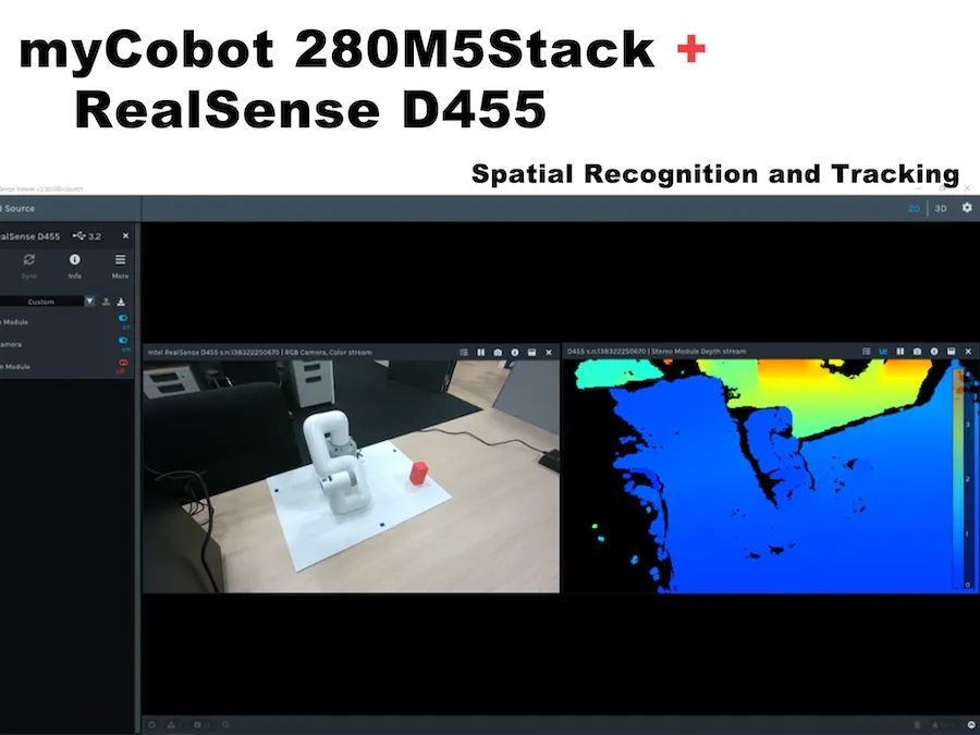
") 使用RealSense D455的空間識別操作myCobot
使用RealSense D455的空間識別操作myCobot

1. 簡介
先進(jìn)技術(shù)部門正在研究多模態(tài)強(qiáng)化學(xué)習(xí),包括相機(jī)圖像和觸覺傳感器。除其他外,要實(shí)現(xiàn)所謂的Sim2Real,其中模擬器中的強(qiáng)化學(xué)習(xí)結(jié)果也在實(shí)際機(jī)器上運(yùn)行,必須協(xié)作操作真實(shí)機(jī)器的機(jī)械臂和相機(jī)。因此,在這種情況下,我們使用ROS測試了鏈接的6軸機(jī)械臂myCobot(由大象機(jī)器人制造)和深度攝像頭RealSense D455(由英特爾制造),流程和結(jié)果將在下面詳細(xì)描述。
操作環(huán)境:
PC:Ubuntu 20.04, ROS Noetic, Python 3.8.10
機(jī)械臂:myCobot280 M5Stack
深度攝像頭:實(shí)感D455
這篇博客描述了如何創(chuàng)建和運(yùn)行一個(gè)簡單的程序,但我假設(shè) ROS 和 Python 環(huán)境已經(jīng)設(shè)置好了。
2. 我的協(xié)作機(jī)器人基礎(chǔ)知識
首先,準(zhǔn)備myCobot,但我有點(diǎn)困惑,因?yàn)橛捎诠碳碌仍颍承┎考谑褂弥邪l(fā)生了變化。這項(xiàng)工作是在 2021 年 3 月左右完成的,當(dāng)時(shí) myStudio 版本是 1.3.<>。我認(rèn)為不會有任何重大變化,但如果您看到不同之處,請參閱官方說明。
運(yùn)行myCobot需要以下三個(gè)準(zhǔn)備工作。
● 更新固件(基本,原子)
● 機(jī)械臂關(guān)節(jié)校準(zhǔn)
● 機(jī)械臂與PC機(jī)之間的串行通信
更新固件
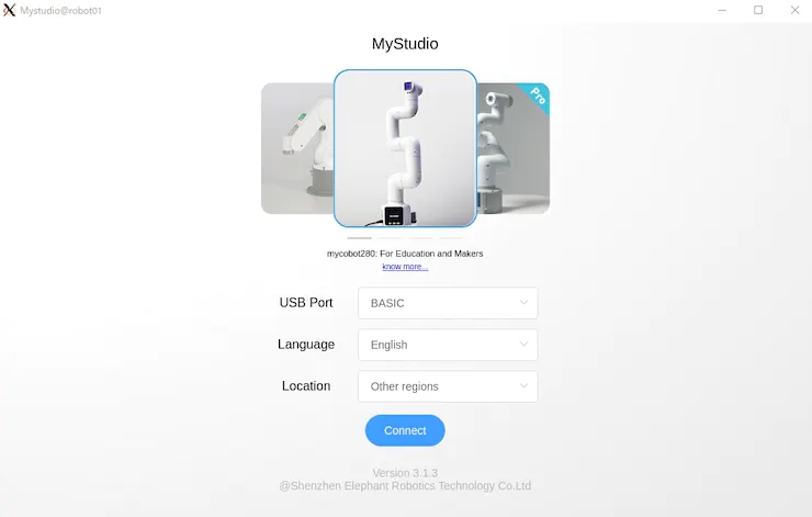
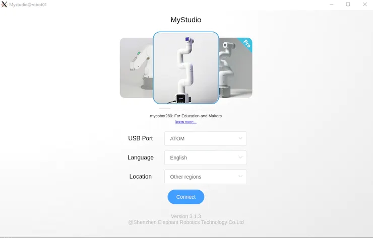
myCobot 280 M5在底座上有一個(gè)M5Stack Basic,在機(jī)械臂的末端有一個(gè)ATOM(Basic,ATOM),用于將固件寫入這兩個(gè)模塊。
首先,使用 USB 連接到 PC,并使用 chmod 允許讀取和寫入設(shè)備。此外,對于Windows或Mac上的USB串行通信,需要安裝特殊的驅(qū)動程序。
$ sudo chmod 666 /dev/ttyUSB*
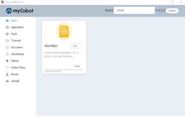
接下來,下載更新的固件應(yīng)用程序-myStudio(在撰寫本文時(shí),最新版本是3.1.4,但僅適用于Windows,3.1.3可用于Linux)。
提取源代碼并執(zhí)行 AppImage 后,它將分別啟動 Basic 和 ATOM。如圖 1 和圖 2 所示。
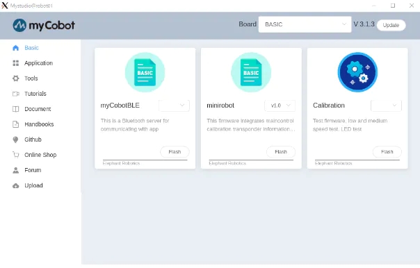
在myStudio 3.1.3中,將出現(xiàn)如圖3和圖4所示的屏幕,然后下載最新版本的Minirobot for Basic和AtomMain for ATOM,選擇Flash,然后寫入固件。使用Basic完成寫入后,迷你機(jī)器人的輸出將顯示在面板上。(請注意,如果您不使用Basic和ATOM編寫最新版本,則機(jī)器人手臂可能無法正常工作)。
更新固件后,下一步是校準(zhǔn)接頭角度。
接頭角度校準(zhǔn)
首先,在“基本”面板中選擇“校準(zhǔn)”,然后按“確定”。
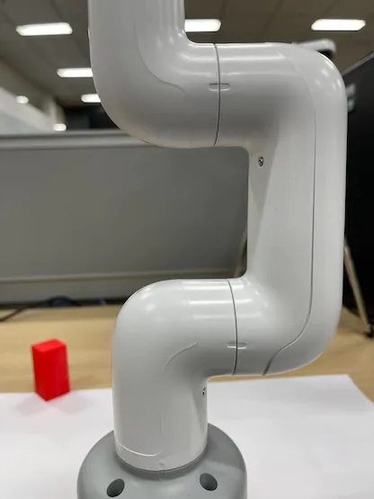
myCobot 的每個(gè)接頭都有一個(gè)代表原點(diǎn)的凹口,如圖 5 所示,因此凹口是手動相互對齊的。
在此狀態(tài)下,在“基本”面板中選擇“校準(zhǔn)伺服”,然后按“下一步”完成校準(zhǔn)。運(yùn)行測試伺服將允許電機(jī)圍繞凹口稍微旋轉(zhuǎn)以確認(rèn)正確校準(zhǔn)。
機(jī)械臂和PC之間的串行通信
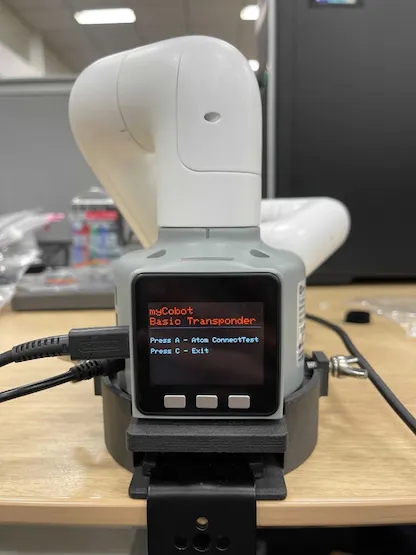
最后,當(dāng)您啟動應(yīng)答器時(shí),您可以通過串行通信從PC操作myCobot。這很容易做到,只需在“基本”面板中選擇應(yīng)答器,然后按“確定”。然后顯示屏將顯示如圖6所示,按基本按鈕。
在“基本”面板的其他菜單中,“基本”中的“主控制”控制 ATOM,“信息”檢查每個(gè)關(guān)節(jié)是否正確連接。當(dāng)myCobot在PC上無法正常工作時(shí),您可以檢查myCobot本身是否存在問題。
3. 蟒蛇接口
準(zhǔn)備完成后,我們可以在PC上操作myCobot。這次,我嘗試了使用 pymycobot 從 python 腳本進(jìn)行操作的方法,以及使用 mycobot_moveit 庫從 ROS 操作 MoveIt 的方法 。
首先,安裝pymycobot。
$ pip install pymycobot --upgrade
您也可以從 Github 下載安裝源代碼。
從源代碼下載時(shí),示例腳本包含在測試目錄中。但是,它不會按原樣工作,因此請小心。我做了下面的例子,而不是重寫。
# mycobot_control_test.py#!/usr/bin/env pythonimport time from pymycobot.mycobot import MyCobotfrom pymycobot.genre import Angle, Coord if __name__ == "__main__":port = "/dev/ttyUSB0"mycobot = MyCobot(port, baudrate="115200", timeout=0.1, debug=False) #After the baud rate are the default values #Get the operation of the joint angleprint("get angles")print(" degrees: {}n".format(mycobot.get_angles()))time.sleep(0.5) print("get radians")print(" radians: {}n".format(mycobot.get_radians()))time.sleep(0.5) print("send angles: [0, 0, 0, 0, -90, 0]")mycobot.send_angles([0, 0, 0, 0, 0, 0], 80)time.sleep(1.5)mycobot.send_angles([0, 0, 0, 0, -90, 0], 80)print(" Is moving: {}n".format(mycobot.is_moving()))time.sleep(1.5) print("send radians: [0, 0, 0, 0, 1.57, 0]n")mycobot.send_radians([0, 0, 0, 0, 1.57, 0], 80)time.sleep(1.5) print("send angle to joint 4: -90n")mycobot.send_angle(Angle.J4.value, -90, 80)time.sleep(1.5) # Operations to get coordinatesprint("get coordination")print(" coordination {}n".format(mycobot.get_coords()))time.sleep(0.5) print("send coordination: [50, 50, 300, 0, 0, 0] → [50, 50, 300, 90, 90, 0]n")coord_list = [50, 50, 300, 0, 0, 0]mycobot.send_coords(coord_lis, 70, 0)time.sleep(3.0)coord_list = [50, 50, 300, 90, 90, 0]mycobot.send_coords(coord_lis ,70, 0)time.sleep(1.5) # Scenarios using grippers# print("open gripper")# mycobot.set_gripper_state(0,0)# time.sleep(1.0)# print("close gripper")# mycobot.set_gripper_state(1,80)# time.sleep(1.0) time.sleep(1.5)print("release all servos")mycobot.release_all_servos()
運(yùn)行mycobot_control_test.py文件
$ python3 mycobot_control_test.py
在 mycobot 模塊中創(chuàng)建 MyCobot 類的實(shí)例,并使用 getter 和 setter 來檢查和更改狀態(tài)。
創(chuàng)建實(shí)例
mycobot = MyCobot(port, baudrate="115200", timeout=0.1, debug=False)
設(shè)置四個(gè)參數(shù)。在波特率之后輸入默認(rèn)值。端口是 USB 串行通信端口。您可以通過在終端中運(yùn)行ls / dev /來查看連接到PC的設(shè)備列表。在Linux中,如果沒有其他用于串行通信的USB端口,它將是/ dev / ttyUSB0。我認(rèn)為Mac和Windows是不同的,所以相應(yīng)地檢查。
關(guān)于吸氣劑
get_angles ( ) 和 get_radians () 是獲取關(guān)節(jié)角度(以度和弧度為單位)的函數(shù)。返回值是六個(gè)關(guān)節(jié)角度值的列表。
還有一個(gè)get_coords( )函數(shù),它獲取以底底中心為原點(diǎn)的坐標(biāo)系*中手臂尖端的坐標(biāo)。返回值是一個(gè) 6 維列表,其中包含尖端的 x、y、z 坐標(biāo) (mm) 和方向 rx、ry、rz(角度)。在沒有 MoveIt 的情況下實(shí)現(xiàn)反向運(yùn)動學(xué)真是太好了。
*坐標(biāo)系:以“基本”面板為背面,每個(gè)正方向分別為 x:向前、y:向左和 z:向上。請注意,MoveIt 中的向量略有不同,稍后將對此進(jìn)行介紹。
關(guān)于二傳手
以度和弧度為單位發(fā)送關(guān)節(jié)角的函數(shù)是send_angles ( ) 和 send_radians ( ),并且具有兩種類型的參數(shù)設(shè)置。
首先,在指定并發(fā)送所有 6 個(gè)關(guān)節(jié)時(shí),第一個(gè)參數(shù)與 getter 相同,在列表類型中放入 6 個(gè)浮點(diǎn)值,第二個(gè)參數(shù)中輸入關(guān)節(jié)運(yùn)動的速度 *(int: 0 ~ 100)。
mycobot .send_angles ( [ 0 , 0 , 0 , 0 , 0 , 0 ] , 80 )
接下來,您取關(guān)節(jié)的角度并發(fā)送它。請將關(guān)節(jié)角度的代碼放在第一個(gè)參數(shù)中,角度值放在第二個(gè)參數(shù)中,速度放在第三個(gè)參數(shù)中。
mycobot .send_angle ( Angle.J4.value , -90,80 )
也可以通過像getter這樣的坐標(biāo)來操作。在這種情況下,放置了 6 個(gè)元素的列表 [x, y, z, rx, ry, rz],第一個(gè)參數(shù)是協(xié)調(diào)的,第二個(gè)參數(shù)是速度,第三個(gè)參數(shù)是模式。模式有兩種類型,0:角度和1:線性
mycobot .send_coords ( [ [ 80 , 50 , 300 , 0 , 90 , 0 ] , 70 , 0 )
由于源代碼中沒有詳細(xì)說明速度單位,因此我認(rèn)為您在必要時(shí)對其進(jìn)行測量。
其他接口
一旦機(jī)械臂移動,電機(jī)將繼續(xù)施加扭矩以試圖保持當(dāng)前狀態(tài),因此如果保持原樣,電機(jī)將過載。因此,讓我們在操作完成后使用函數(shù)release_all_servos(y)釋放電機(jī)扭矩。
如果機(jī)器人手臂正在運(yùn)行,并且您指示它執(zhí)行另一個(gè)操作,則會發(fā)生錯誤,它將繼續(xù)執(zhí)行下一個(gè)操作。在示例腳本中,python內(nèi)置函數(shù)time.sleep()用于等待每個(gè)動作完成,但您可以使用函數(shù)is_moving()來獲取電機(jī)是否正在運(yùn)行,以便您可以循環(huán)while等。(我認(rèn)為這個(gè)函數(shù)是錯誤,并返回一個(gè)不斷移動的狀態(tài)。
還有一些其他 API 可用于打開和關(guān)閉電源、更改 LED 的顏色以及檢查電機(jī)狀態(tài),但這次我省略了它們,因?yàn)槟繕?biāo)是移動手臂。
4. 只讀標(biāo)準(zhǔn)
接下來,在ROS中使用MoveIt來操縱myCobot。
大象機(jī)器人實(shí)現(xiàn)mycobot的動作它可以安裝并可以安裝
有一個(gè)MoveIt的志愿者實(shí)現(xiàn),我決定使用它。安裝是根據(jù)上面的 GitHub 自述文件編寫的。
$ cd /src$ git clone https://github.com/Tiryoh/mycobot_ros$ git clone https://github.com/nisshan-x/mycobot_moveit$ rosdep update$ rosdep install -i –from-paths mycobot_moveit$ cd .$ catkin_make #Set up work area$ source devel/setup.bash
完成安裝和設(shè)置工作區(qū)后
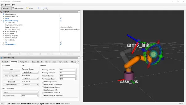
$ roslaunch mycobot_moveit mycobot_moveit_control.launch
MoveIt 和 Rviz GUI 將啟動,如圖 7 所示。通過拖放綠色球,計(jì)算出機(jī)器人手臂末端位置的姿勢,然后按下左下角的計(jì)劃和執(zhí)行按鈕,Rviz 與實(shí)際機(jī)器人一起移動。
* 當(dāng)模型和實(shí)際機(jī)器不能一起工作時(shí)
我不知道這是否是所有環(huán)境中都會發(fā)生的錯誤,并且模型和真實(shí)機(jī)器并不總是協(xié)同工作。這是電機(jī)旋轉(zhuǎn)方向反轉(zhuǎn)時(shí)發(fā)生的錯誤,所以有點(diǎn)棘手,但請將模型與真機(jī)進(jìn)行比較,尋找相反方向的關(guān)節(jié)旋轉(zhuǎn)。
確認(rèn)有多少關(guān)節(jié)沿相反方向旋轉(zhuǎn)后,重寫描述機(jī)器人模型的 URDF 文件。
/ src / mycobot_moveit / urdf / mycobot_urdf_gazebo.urdf
定義的聯(lián)合信息的說明如下。
mycobot_urdf_gazebo.urdf ~~ ~~
Arm1 ~ arm6_joint 相同的說明。旋轉(zhuǎn)軸的方向設(shè)置為<軸xyz = “0 0 1”> ,并且設(shè)置1→-1反轉(zhuǎn)關(guān)節(jié)在相反方向上的旋轉(zhuǎn)。
在我的環(huán)境中,似乎除了第三個(gè)關(guān)節(jié)之外的所有關(guān)節(jié)都是反轉(zhuǎn)的。我不知道這是因?yàn)闄C(jī)器人舵機(jī)的個(gè)體差異還是其他原因,如果您知道,請告訴我。
這就是它的全部內(nèi)容,從myCobot設(shè)置到操作基礎(chǔ)。
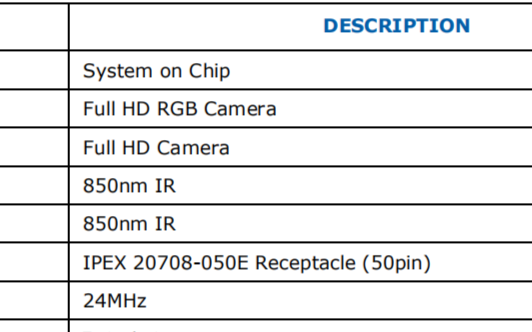
5. 現(xiàn)實(shí)D455基礎(chǔ)知識
這次我用D455進(jìn)行了測試,但基本上D400系列可以以相同的方式使用。只有D435i和D455內(nèi)置了IMU傳感器,但本文沒有用到(因?yàn)檎`差累積的缺點(diǎn)比在固定狀態(tài)下使用IMU的優(yōu)點(diǎn)更明顯)。除了帶有紅外立體攝像頭的D400系列外,還有帶有LiDAR的L515,但用途相同。另外,我認(rèn)為新的性能最好,所以我會買D455。我認(rèn)為最好在購買前咨詢一下您想使用的環(huán)境,因?yàn)橛幸恍┝慵ㄒ郧暗男吞柣旧鲜窍蚝蠹嫒莸模栽趦r(jià)格和性能之間有一個(gè)權(quán)衡)。
查看器的軟件安裝和基本操作
安裝庫 librealsense 以運(yùn)行實(shí)感。 沒有這個(gè),后面將描述的realsense_ros將無法工作。有一個(gè)關(guān)于如何在 Linux 上安裝它的文檔。如果需要,Windows 上的安裝方法也位于同一文檔庫中。
# Server Public Key Registration$ sudo apt-key adv –keyserver keyserver.ubuntu.com –recv-key F6E65AC044F831AC80A06380C8B3A55A6F3EFCDE|| Adding a Repository$ sudo add-apt-repository “deb https://librealsense.intel.com/Debian/apt- repo $(lsb_release -cs) main” -u# install lib$ sudo apt install librealsense2-dkms librealsense2- utils# install dev$ sudo apt install librealsense2-dev librealsense2-dbg
安裝完成后,在終端中運(yùn)行實(shí)感查看器進(jìn)行查看。如果它不起作用,請嘗試拔下并插入實(shí)感 USB 連接并重新啟動 PC。如果啟動成功,將顯示查看器,如圖 8 所示。
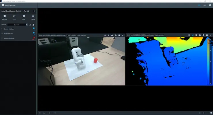
您可以使用右上角的 2D | 3D 按鈕在 2D 和 3D 之間切換查看器。此外,您可以通過打開左側(cè)的立體模塊和RGB攝像頭來查看深度信息和RGB信息。在 2D 中,您可以在 2D 中查看 RGB 和深度信息。在3D中,由深度估計(jì)紅外立體相機(jī)估計(jì)的點(diǎn)云用深度彩色圖和RGB相機(jī)信息著色,可以從各個(gè)角度查看。此外,內(nèi)置 IMU 傳感器的 D435i 和 D455 還可以通過運(yùn)動模塊獲取姿態(tài)信息。接下來,我們來看看使用 ROS 包realsense_ros的 Rviz 點(diǎn)云。這可以使用 apt 安裝。
$ sudo apt install ros-$ROS_DISTRO-realsense2-camera
實(shí)感攝像頭在第一個(gè)終端啟動,除了每個(gè)攝像頭的信息外,還提供彩色點(diǎn)云,在第二個(gè)終端上啟動 Rviz 進(jìn)行可視化。
$ roslaunch realsense2_camera rs_camera.launch filter:=pointcloud$rviz
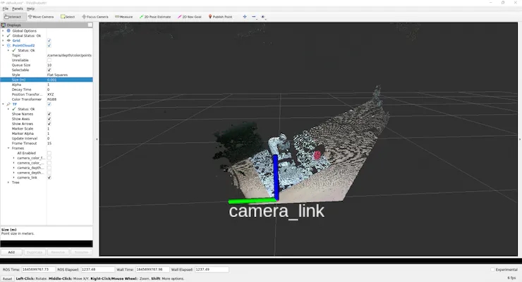
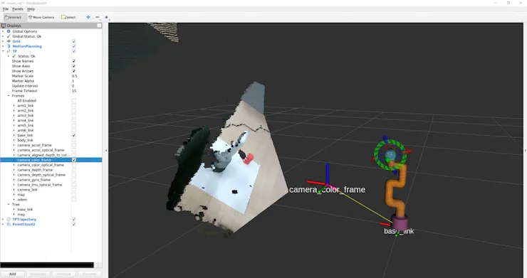
為了如圖 9 所示查看點(diǎn)云,我們將使用 GUI 來調(diào)整設(shè)置。
首先,由于左側(cè)顯示面板中的全局選項(xiàng)的 固定框是地圖,請單擊它并將其更改為camera_link。
然后按顯示面板底部的添加按鈕,將彈出一個(gè)新窗口,列出可以在 Rviz 中顯示的 ROS 消息類型。選擇 rviz 組中間的 PointCloud2,然后按 OK 將 PointCloud2 添加到顯示面板。
此外,如果您單擊組中“主題”列右側(cè)的空白并選擇出現(xiàn)的 /camera/depth/color/points,則點(diǎn)云將顯示在 Rviz 上。默認(rèn)情況下,點(diǎn)云大小設(shè)置為 0.01 m,這是一個(gè)很大的值,因此點(diǎn)云相互重疊顯示,但如果將其設(shè)置為 0.001 m 左右,您可以看到點(diǎn)云的獲取非常精細(xì)。
此外,如果從“添加”中選擇“TF”并添加它,則可以顯示攝像機(jī)位置和方向(軸向)。默認(rèn)情況下,RGB 相機(jī)原點(diǎn)和立體相機(jī)原點(diǎn)分別顯示在世界坐標(biāo)系和光學(xué)坐標(biāo)系中。(camera_link似乎與立體相機(jī)起源相同)
保存設(shè)置,因?yàn)楹茈y每次都彈出此按鈕。
在工作區(qū)中創(chuàng)建目錄配置以保存設(shè)置,在 Rviz 的文件中選擇將配置另存為,命名創(chuàng)建的配置目錄并保存。
$ rviz -d .rviz
如果您更改了某些內(nèi)容,則可以每次通過保存配置更新相同的文件。如果您只是查看點(diǎn)云和相機(jī)位置,您可以使用realsense_viewer輕松做到這一點(diǎn),但您可以使用 ROS 來處理原始數(shù)據(jù)。從這里開始就像是理解 ROS 消息數(shù)據(jù)含義的練習(xí)。
(但是,就個(gè)人而言,這是一個(gè)很大的絆腳石)
執(zhí)行rs_camera.launch過濾器后:=點(diǎn)云。
讓我們看一下 從另一個(gè)終端發(fā)送的 /camera/depth/color/points 主題的原始數(shù)據(jù)。
$ rostopic echo /camera/depth/color/points
當(dāng)然這個(gè)值數(shù)組是點(diǎn)云數(shù)據(jù),它應(yīng)該用 xyz 坐標(biāo)和位置中的 RGB 值表示,但很難直接讀取。如果您查看數(shù)字,您會發(fā)現(xiàn)每個(gè)值都在 0 到 255 的范圍內(nèi),并且類似的值以常規(guī)模式定期出現(xiàn)。但是,從這里猜測 x 代表哪里以及紅色代表哪里是不合理的。
因此,首先,找出此消息的類型。
$ rostopic type /camera/depth/color/pointssensor_msgs/PointCloud2
我們現(xiàn)在知道消息類型是 sensor_msgs/PointCloud2。
另外,如果您從 ROS 文檔中查看它,您可以看到如下內(nèi)容。
Header header # header uint32 height # number of rows of datauint32 width # Number of columns of dataPointField[] fields # 1 point data structurebool is_bigendian # whether the big enduint32 point_step # number of bytes in a point (number of 8-bit numbers)uint32 row_step # number of data in a row (= width * point_step)uint8[] data # raw data (8bit row_step * height data array)bool is_dense # if true, then no invalid data
既然是點(diǎn)云,那么與2D圖像不同,數(shù)據(jù)的順序有什么意義?正如問題所暗示的那樣,高度和寬度似乎沒有意義。
目前尚不清楚持有可以從其他值計(jì)算并且不太可能使用的變量意味著什么,但結(jié)構(gòu)是這樣的。如果要查看每個(gè)的實(shí)際值,
$ rostopic echo /camera/depth/color/points/
通過執(zhí)行此操作,您只能在數(shù)據(jù)中輸出一個(gè)變量。例如,顯示回point_step和字段給出。
$ rostopic echo /camera/depth/color/points/point_step–20—$ rostopic echo /camera/depth/color/points/fields–name: “x”offset: 0datatype: 7count: 1–name: “y”offset: 4datatype: 7count: 1–name: “z”offset: 8datatype: 7count: 1–name: “rgb”offset: 16datatype: 7count: 1—
輸出將是 由于 point_step = 20,您可以看到一個(gè)點(diǎn)的數(shù)據(jù)由 20 個(gè)字節(jié)表示,您可以從字段的內(nèi)容中看到這 20 個(gè)字節(jié)是如何組成的。
每個(gè)變量的含義是
名稱:要表示的數(shù)據(jù)的名稱
偏移量:對應(yīng)的字節(jié)
數(shù)據(jù)類型:所表示數(shù)據(jù)的類型代碼
計(jì)數(shù):包含的數(shù)據(jù)項(xiàng)數(shù)
例如,x 坐標(biāo)對應(yīng)于從 0 到 3 的數(shù)據(jù),類型代碼為 7(對應(yīng)于 float32),表示數(shù)據(jù)。 y 和 z 應(yīng)該以相同的方式處理,但 RGB 也以相同的方式表示。當(dāng)我查看與 RGB 對應(yīng)的第 16 個(gè)到第 19 個(gè)值時(shí),有 GBRA 順序的十六進(jìn)制值。到 float32 的轉(zhuǎn)換似乎很難處理,因此似乎需要單獨(dú)處理 xyz 坐標(biāo)和 RGB。
現(xiàn)在我們知道了如何表示數(shù)據(jù),讓我們實(shí)際處理它。
(我認(rèn)為有一個(gè)更智能,更快捷的方法來處理下一個(gè)腳本,所以如果你有任何建議,請)
將腳本目錄添加到mycobot_test包中,并在其中添加 python 腳本。
$ cd /src/mycobot_test$ mkdir scripts$ cd scripts$ touch red_point_detection.py$ touch object_position_search.py
將依賴項(xiàng)添加到 CMakeLists.txt 并打包.xml。
# CMakeLists.txtfind_package(catkin REQUIRED COMPONENTS # Add rospy and sensor_msgs modules to be able to import rospy sensor_msgs ) catkin_package( # Add build package sensor_msgs ) # Add scripts to the executable directory catkin_install_python(PROGRAMS DESTINATION ${CATKIN_PACKAGE_BIN_DESTINATION}/scripts )Python rospy sensor_msgs rospy sensor_msgs
以下red_point_detection.py是一個(gè)腳本,它僅從點(diǎn)云中提取紅色并創(chuàng)建新消息。
#!/usr/bin/env python3 import time, os, sys, signal, threading import numpy as np import rospy from sensor_msgs.msg import PointCloud2 class RedPointsDetectionNode(object): def __init__(self): super(RedPointsDetectionNode, self).__init__() self.data = PointCloud2() self.point_step = 20 self.R_COL = 18 self.G_COL = 17 self.B_COL = 16 rospy.init_node("red_points_detection_node") rospy.loginfo("red points detection start") # Subscriber def sub_pointcloud(self): def callback(data): self.sub_data = data sub = rospy.Subscriber("camera/depth/color/points", PointCloud2, callback = callback) rospy.spin() # Publisher def pub_red_pointcloud(self): pub = rospy.Publisher("red_point_cloud", PointCloud2, queue_size = 1) while not rospy.is_shutdown(): pub_data = self.red_point_detection(self.sub_data) pub.publish(pub_data) def red_point_detection(sub_data): red_point_data = sub_data red_pointcloud = np.array([d for d in sub_data.data]).reshape(-1, self.point_step) r_flags = red_pointcloud < 180 g_flags = red_pointcloud > 150 b_flags = red_pointcloud > 150 R_under_threshold_row = np.where(r_flags)[0][np.where(np.where(r_flags)[1]==self.R_COL)] G_over_threshold_row = np.where(g_flags)[0][np.where(np.where(g_flags)[1]==self.G_COL)] B_over_threshold_row = np.where(b_flags)[0][np.where(np.where(b_flags)[1]==self.B_COL)] not_red_row = np.unique(np.concatenate([R_under_threshold_row, G_over_threshold_row, B_over_threshold_row])) red_pointcloud = np.delete(red_pointcloud, not_red_row, axis=0).ravel().tolist() red_point_data.width = int(len(red_pointcloud) / self.point_step) red_point_data.height = 1 red_point_data.row_step = pub_pc2_data.width * self.point_step red_point_data.data = red_pointcloud rospy.loginfo("red pointcloud {}".format(int(len(red_pointcloud) / self.point_step))) return red_point_data # node start to subscribe and publish def start_node(self): sub_pointcloud = threading.Thread(target = self.sub_pointcloud) pub_red_pointcloud = threading.Thread(target = self.pub_red_pointcloud) sub_pointcloud.setDaemon(True) sub_pointcloud.start() pub_red_pointcloud.setDaemon(True) pub_red_pointcloud.start() sub_pointcloud.join() pub_red_pointcloud.join() if __name__ == "__main__": color_points_detector = ColorPointsDetectionNode() color_points_detector.start_node() pass
訂閱者讀取相機(jī)/深度/顏色/點(diǎn)數(shù)據(jù),發(fā)布者僅從數(shù)據(jù)中提取紅點(diǎn)并分發(fā)它們。處理紅點(diǎn)以從原始點(diǎn)云中刪除 RGB 值為f R < 180、G > 150 和 B > 150 的點(diǎn)。使用HSV比RGB更好,RGB容易受到照明條件的影響,但是這次在處理PointCloud2數(shù)據(jù)時(shí)很難轉(zhuǎn)換為HSV,因此被擱置了。如果是C++,使用 PCL 似乎很容易進(jìn)行 python 轉(zhuǎn)換,但對于 python 來說毫無用處,因?yàn)楹茈y編寫其他過程)。
寫入后,將其移動到工作區(qū),catkin_make并執(zhí)行它。
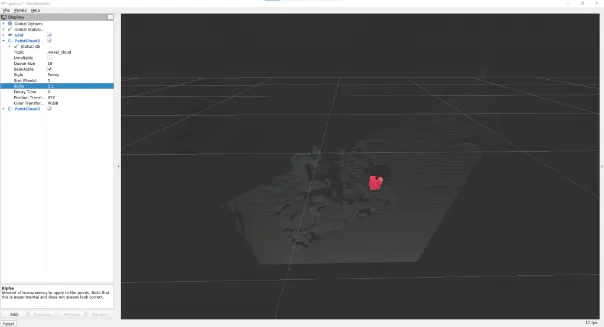
$ roslaunch realsense2_camera rs_camera.launch filters:=pointcloud$ rosrun mycobot_test red_point_detection.py$ rviz -d .rviz
如果在 Rviz 中選擇添加到 PointCloud2 消息中的 /red_point_cloud,則可以看到提取的點(diǎn)云,如圖 10 所示。
object_position_search.py是一個(gè)腳本,用于查找提取的紅點(diǎn)坐標(biāo)的平均值。
# object_position_search.py#!/usr/bin/env python3 import time, os, sys, signal, threading import numpy as np import rospy from sensor_msgs.msg import PointCloud2 import sensor_msgs.point_cloud2 as pc2 from geometry_msgs.msg import Point class ObjectPositionSearchNode(object): def __init__(self): super(ObjectPositionSearchNode, self).__init__() rospy.init_node("object_position_search_node") rospy.loginfo("object position search start") self.object_position = Point() # Subscriber def sub_pointcloud(self): def callback(data): rospy.loginfo("subscribed pointcloud") xyz_generator = pc2.read_points(data, field_names = ("x", "y", "z"), skip_nans=True) xyz_list = [gen for gen in xyz_generator] list_num = len(xyz_list) x = np.array([xyz_list[i][0] for i in range(list_num) if (xyz_list[i][2] < 1.0 and xyz_list[i][2] > -1.0)]) y = np.array([xyz_list[i][1] for i in range(list_num) if (xyz_list[i][2] < 1.0 and xyz_list[i][2] > -1.0)]) z = np.array([xyz_list[i][2] for i in range(list_num) if (xyz_list[i][2] < 1.0 and xyz_list[i][2] > -1.0)]) self.object_position.x = np.average(x) self.object_position.y = np.average(y) self.object_position.z = np.average(z) sub = rospy.Subscriber("red_point_cloud", PointCloud2, callback = callback) rospy.spin() # Publisher def pub_target_position(self): pub = rospy.Publisher("object_position", Point, queue_size=1) while not rospy.is_shutdown(): rospy.loginfo("published object position: {:.5f}, {:.5f}, {:.5f}n".format(self.object_position.x, self.object_position.y, self.object_position.z)) pub.publish(self.object_position) def start_node(self): sub_pointcloud = threading.Thread(target = self.sub_pointcloud) pub_target_position = threading.Thread(target = self.pub_target_position) sub_pointcloud.setDaemon(True) sub_pointcloud.start() pub_target_position.setDaemon(True) pub_target_position.start() sub_pointcloud.join() pub_target_position.join() if __name__ == "__main__": object_position_searcher = ObjectPositionSearchNode() object_position_searcher.start_node() pass
在之前運(yùn)行red_point_search.py的情況下,啟動一個(gè)新終端并運(yùn)行它。
$ rosrun mycobot_test object_position_search.py
它取red_point_cloud坐標(biāo)值的平均值 并分布它們,同時(shí)記錄這些值。坐標(biāo)以米為單位,此腳本檢索 1.0 米內(nèi)的點(diǎn)。由于使用 rospy.loginfo 獲得的坐標(biāo)被記錄下來,因此坐標(biāo)被輸出到終端。
sensor_msgs庫中有一個(gè)point_cloud2模塊,用于處理和讀取 PointCloud2 數(shù)據(jù),將坐標(biāo)值從 4Byte 轉(zhuǎn)換為 float32。內(nèi)容很簡單,但我很難理解這個(gè)模塊的存在。如果您有其他復(fù)雜的消息數(shù)據(jù),最好查看是否有隨附的處理模塊。這是真正意義上的設(shè)置和數(shù)據(jù)處理。關(guān)于數(shù)據(jù)處理,我認(rèn)為您仍然需要找到更快處理(或改進(jìn)算法)的方法,具體取決于應(yīng)用程序。
6. 使用 ROS 將 myCobot 連接到實(shí)感 D455
現(xiàn)在實(shí)感數(shù)據(jù)處理已經(jīng)完成,我想將其與myCobot結(jié)合使用。因此,最重要的是從實(shí)感相機(jī)坐標(biāo)系到myCobot坐標(biāo)系的轉(zhuǎn)換。Rviz 上有一個(gè) TF(變換)顯示相機(jī)軸,但您需要了解這一點(diǎn)。顧名思義,它描述了描述一個(gè)坐標(biāo)系與另一個(gè)坐標(biāo)系之間關(guān)系的坐標(biāo)變換。首先,讓我們看看如果未設(shè)置此 TF 會發(fā)生什么情況。
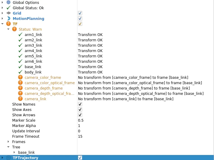
$ roslaunch realsense2_camera rs_camera.launch filter:=pointcloud$ roslaunch mycobot_moveit mycobot_moveit_control.launch
然后,您將在 Rviz 顯示面板中看到一條警告,如圖 11 所示。消息是相機(jī)的每個(gè)坐標(biāo)系都沒有變換到base_link(myCobot的起源)。
因此,讓我們創(chuàng)建一個(gè)包,將 TF(坐標(biāo)變換)從相機(jī)廣播到 myCobot。很抱歉在C++和Python之間來回,但這次我將使用roscpp。首先創(chuàng)建一個(gè)包。
$ cd /src$ catkin_create_pkg tf_broadcaster roscpp$ cd tf_broadcaster$ touch src/tf_broadcaster.cpp
重寫生成的tf_broadcaster.cpp CMakeLists.txt、package.xml如下所示。請注意,C++文件是一個(gè)類,因?yàn)樗菫榱司毩?xí)在類中創(chuàng)建節(jié)點(diǎn)而創(chuàng)建的,但可以更輕松地編寫。
// tf_broadcaster.cpp#include #include #include #include class TfBroadcaster { public: TfBroadcaster(); ~TfBroadcaster(); // Broadcast void BroadcastStaticTfFromCameraToMyCobot(); private: ros::NodeHandle nh_; // TF Broadcaster tf2_ros::StaticTransformBroadcaster static_tf_broadcaster_; // constant double PI_ = 3.1419265; }; TfBroadcaster::TfBroadcaster(){} TfBroadcaster::~TfBroadcaster(){} void TfMyCobotBroadcaster::BroadcastStaticTfFromCameraToMyCobot() { geometry_msgs::TransformStamped transformStamped; transformStamped.header.stamp = ros::Time::now(); transformStamped.header.frame_id = "camera_color_frame"; //link transformStamped.child_frame_id = "base_link"; // son link // Parallel movement transformStamped.transform.translation.x = -0.3; transformStamped.transform.translation.y = -0.3; transformStamped.transform.translation.z = -0.3; // Turning back tf2::Quaternion q; q.setEuler(0, 0, 0); transformStamped.transform.rotation.x = q.x(); transformStamped.transform.rotation.y = q.y(); transformStamped.transform.rotation.z = q.z(); transformStamped.transform.rotation.w = q.w(); static_tf_broadcaster_.sendTransform(transformStamped); } int main(int argc, char** argv) { ros::init(argc, argv, "tf_mycobot_broadcaster"); TfMyCobotBroadcaster tf_mycobot_broadcaster; tf_mycobot_broadcaster.BroadcastStaticTfFromCameraToMyCobot(); ros::Rate loop_rate(10); while(ros::ok()){ ros::spinOnce(); loop_rate.sleep(); } return 0; }# CMakeLists.txtcmake_minimum_required(VERSION 3.0.2) project(tf_broadcaster) find_package(catkin REQUIRED COMPONENTS roscpp geometry_msgs tf2_geometry_msgs) catkin_package( CATKIN_DEPENDS geometry_msgs tf2_geometry_msgs) include_directories(${catkin_INCLUDE_DIRS}) add_executable(tf_mycobot_broadcaster src/tf_mycobot_broadcaster.cpp) target_link_libraries(tf_mycobot_broadcaster ${catkin_LIBRARIES}) tf_broadcaster 0.0.0 The transform broadcaster package root TODO catkin tf2_geometry_msgs geometry_msgs
如您所見,我們設(shè)置 transformStamped 類的實(shí)例變量并廣播該實(shí)例。廣播變量類型是tf2_ros::StaticTransformBroadcaster,但這次我們使用靜態(tài)TF,因?yàn)閿z像機(jī)和機(jī)器人的位置是固定的。對于那些感興趣的人,當(dāng)職位關(guān)系隨時(shí)間變化時(shí),也可以使用動態(tài) TF。
在這里,位置關(guān)系還不知道,所以值是暫時(shí)的,但我們可以組成顯示,所以讓我們嘗試一下。此外,父鏈接camera_color_frame而不是camera_link,因?yàn)楦告溄拥脑c(diǎn)與點(diǎn)云坐標(biāo)系匹配。 catkin_make后,像以前一樣運(yùn)行 rs_camera.launch 和 mycobot_moveit_control.launch,并在另一個(gè)終端中運(yùn)行tf_broadcaster。
$ rosrun tf_broadcaster tf_broadcaster
這將廣播成像儀和myCobot base_link之間的位置關(guān)系,因此TF警告消失。如果在此狀態(tài)下添加點(diǎn)云,它將如圖 12 所示。當(dāng)然,相機(jī)和myCobot之間的位置關(guān)系是暫時(shí)的,因此相機(jī)看到的myCobot位置與Rviz中顯示的模型位置不重疊。
因此,接下來我們將校準(zhǔn)從相機(jī)中看到的機(jī)器人的相對姿勢和位置。
我認(rèn)為還有另一種通過將相機(jī)固定在特定位置來指定位置關(guān)系的方法,但是這次我們標(biāo)記三個(gè)點(diǎn)以確定機(jī)器人坐標(biāo),我們通過找到單位向量并相對于相機(jī)坐標(biāo)系進(jìn)行計(jì)算來校準(zhǔn)位置關(guān)系。
你們中的一些人可能已經(jīng)注意到,之前的照片是在已經(jīng)連接標(biāo)記的情況下拍攝的,但標(biāo)記的放置方式如圖 13 所示。
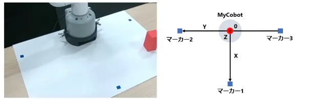
口糧標(biāo)記
myCobot 的原點(diǎn)(底部中心)位于標(biāo)記 2 和 3 的中點(diǎn),標(biāo)記 1 垂直于該原點(diǎn)的線段 2 和 3。
1.首先,重寫red_point_detection.py并創(chuàng)建blue_point_detection.py以獲得藍(lán)色標(biāo)記的點(diǎn)云。此處省略了該腳本,因?yàn)樗皇侵貙懥艘崛〉?RGB 范圍。之后,我認(rèn)為有多種方法可以從那里獲得坐標(biāo)轉(zhuǎn)換,但這次是通過以下過程獲得的。確定標(biāo)記坐標(biāo) 訂閱標(biāo)記點(diǎn)云
一個(gè)。將點(diǎn)云聚類為三個(gè)(通過 k 均值方法)
2. 確定原點(diǎn)和單位向量 標(biāo)記 2 和 3 的中點(diǎn)是原點(diǎn)V_robot
一個(gè)。X 和 Y 的單位向量V_X和V_Y分別V_robot →標(biāo)記 1、V_robot →標(biāo)記 2。
b.Z 的單位向量是帶有標(biāo)記的平面和法線向量的叉積
3. 使用歐拉角創(chuàng)建從相機(jī)姿勢到機(jī)器人姿勢的旋轉(zhuǎn) theta_1 = 相機(jī)相對于水平面的仰角
a.theta_2 = 朝向相機(jī)前方的旋轉(zhuǎn)角度
b.theta_3 = 相機(jī)與機(jī)器人前方方向之間的角度
4. 將 V-Z 方向的原點(diǎn)轉(zhuǎn)換為 myCobot 的固定底座(2.7 厘米)
* 歐拉旋轉(zhuǎn)開始的軸是任意的,因此結(jié)果會因所使用的庫而異。(我認(rèn)為不是每個(gè)人都費(fèi)心這樣做,所以我想知道您是否傳遞單位向量和兩個(gè)坐標(biāo)系的原點(diǎn),如果有一些庫將其轉(zhuǎn)換為 TF。
以下腳本將添加到腳本目錄中。
# mycobot_position_calibration.py#!/usr/bin/env python3 import time, os, sys, signal, threading import numpy as np import rospy from sensor_msgs.msg import PointCloud2 from geometry_msgs.msg import Point import sensor_msgs.point_cloud2 as pc2 class MyCobotPositionCalibrationNode(object): def __init__(self): super(MyCobotPositionCalibrationNode, self).__init__() rospy.init_node("mycobot_position_calibration_node") rospy.loginfo("mycobot position calibration start") # Subscriber def sub_pointcloud(self): def callback(data): self.data = data rospy.loginfo("subscribed pointcloud") xyz_generator = pc2.read_points(self.data, field_names = ("x", "y", "z"), skip_nans=True) xyz_list = [xyz for xyz in xyz_generator if (abs(xyz[0]) < 0.8 and abs(xyz[1]) < 0.8 and abs(xyz[2]) < 0.8)] xyz_array = np.array(xyz_list) if len(xyz_list) > 3: marker_centroids = self.kmeans(3, xyz_array) rospy.loginfo("n marker positionsn{}".format(marker_centroids)) translation = self.cal_translation(marker_centroids) rospy.loginfo("n translationn{}".format(translation)) sub = rospy.Subscriber("blue_point_cloud", PointCloud2, callback = callback) rospy.spin() # node start def start_node(self): sub_pointcloud = threading.Thread(target = self.sub_pointcloud) sub_pointcloud.setDaemon(True) sub_pointcloud.start() sub_pointcloud.join() # clustering method def kmeans(self, k, X, max_iter=30): # k: cluster num, X: numpy array data_size, n_features = X.shape centroids = X[np.random.choice(data_size, k)] new_centroids = np.zeros((k, n_features)) cluster = np.zeros(data_size) for epoch in range(max_iter): for i in range(data_size): distances = np.sum((centroids - X[i]) ** 2, axis=1) cluster[i] = np.argsort(distances)[0] for j in range(k): new_centroids[j] = X[cluster==j].mean(axis=0) if np.sum(new_centroids == centroids) == k: break centroids = new_centroids max_norm = 0 min_norm = 0 sorted_centroids = [] for centroid in centroids: norm = centroid[2] if norm > max_norm: sorted_centroids.append(centroid) max_norm = norm if min_norm == 0: min_norm = sorted_centroids[0][2] else: if norm > min_norm and min_norm != 0: sorted_centroids.insert(1, centroid) else: sorted_centroids.insert(0, centroid) min_norm = norm sorted_centroids = np.array(sorted_centroids) return sorted_centroids # translation angles calculation ## calculation def cal_translation(self, marker_points): # マーカー1, 2, 3の位置ベクトル #Position vector of marker 1, 2, 3 a_1, a_2, a_3 = marker_points # カメラからロボットへのベクトル #Vector from camera to robot V_robot = self.cal_robot_position_vector(a_2, a_3) # ロボットのXYZ単位ベクトル #XYZ unit vector of the robot V_X = (a_2 - V_robot) / (np.linalg.norm(a_2 - V_robot)) V_Y = (a_1 - V_robot) / (np.linalg.norm(a_1 - V_robot)) V_Z = self.cal_normal_vector(marker_points) # カメラの水平面に対する仰角 # Elevation angle of the camera relative to the horizontal plane theta_1 = - (np.pi/2 - self.cal_subtended_angle(-V_robot, V_Z)) # カメラの正面方向の回転角 #Rotation angle of the camera in the frontal direction V_Y_camera = np.array([0, 1, 0]) V_Y_camera_rotated = self.cal_rotate_vector_xaxis(V_Y_camera, -theta_1) theta_2 = - self.cal_subtended_angle(V_Z, -V_Y_camera_rotated) # カメラとロボットのそれぞれの正面方向とのなす角 #Angle between the camera and the respective frontal direction of the robot _, V_robot_projected_to_plane = self.cal_vector_projection(V_robot, V_Z) theta_3 = self.cal_subtended_angle(V_Y, V_robot_projected_to_plane) # mycobotの位置を土臺の高さ0.027 m, V_Z方向に平行移動 # mycobot position at foundation height 0.027 m, parallel to V_Z direction V_robot = V_robot + 0.027*V_Z return V_robot, theta_1, theta_2, theta_3 ## vector and angle caluculation def cal_robot_position_vector(self, a_2, a_3): return (a_2 + a_3) / 2 def cal_normal_vector(self, marker_points): a_1 = marker_points[0] a_2 = marker_points[1] a_3 = marker_points[2] A_12 = a_2 - a_1 A_13 = a_3 - a_1 cross = np.cross(A_13, A_12) return cross / np.linalg.norm(cross) def cal_subtended_angle(self, vec_1, vec_2): dot = np.dot(vec_1, vec_2) norm_1 = np.linalg.norm(vec_1) norm_2 = np.linalg.norm(vec_2) return np.arccos( dot / (norm_1 * norm_2) ) def cal_vector_projection(self, org_vec, normal_vec): # org_vec: 射影したいベクトル # org_vec: the vector you want to project # normal_vec: 射影したい平面の法線ベクトル # normal_vec: Normal vector of the plane to be projected projected_to_vertical = np.dot(org_vec, normal_vec) * normal_vec projected_to_horizontal = org_vec + projected_to_vertical return projected_to_vertical, projected_to_horizontal def cal_rotate_vector_xaxis(self, vec, angle): rotate_mat = np.array([[1, 0, 0], [0, np.cos(angle), np.sin(angle)], [0, -np.sin(angle), np.cos(angle)]]) return vec.dot(rotate_mat) def cal_rotate_vector_yaxis(self, vec, angle): rotate_mat = np.array([[np.cos(angle), 0, -np.sin(angle)], [0, 1, 0], [np.sin(angle), 0, np.cos(angle)]]) return vec.dot(rotate_mat) def cal_rotate_vector_zaxis(self, vec, angle): rotate_mat = np.array([[np.cos(angle), np.sin(angle), 0], [-np.sin(angle), np.cos(angle), 0], [0, 0, 1]]) return vec.dot(rotate_mat) if __name__ == "__main__": mycobot_position_calibrator = MyCobotPositionCalibrationNode() mycobot_position_calibrator.start_node() pass
這次我們從最近的marker_1設(shè)置相機(jī)和機(jī)器人,根據(jù)它們的位置關(guān)系marker_2和marker_3,但需要注意的是,需要根據(jù)相機(jī)的位置進(jìn)行調(diào)整。
構(gòu)建完成后,相機(jī)、顏色搜索和校準(zhǔn)節(jié)點(diǎn)將在三個(gè)終端中分別啟動。
$ roslaunch realsense2_camera rs_camera.launch filter:=pointcloud$ rosrun mycobot_test blue_point_detection.py$ rosrun mycobot_test mycobot_position_calibration.py
這將記錄變換 t_x, y, z (m) 和歐拉角 theta_1, 2, 3 (弧度) 到 mycobot_position_calibration.py 的終端。這些值由于點(diǎn)云數(shù)據(jù)收集和聚類而波動,因此這些值被多次取平均值。(在此設(shè)置中,平行平移和歐拉角都波動約 1%)
獲取值后,在 tf_broadcaster.cpp 中重寫臨時(shí)值。
// tf_broadcaster.cpp~~ # それぞれ t_x,y,z と theta_1,_2,_3 に得られた値を入れる # Put the obtained values in t_x,y,z and theta_1,_2,_3 respectively transformStamped.transform.translation.x = t_z; transformStamped.transform.translation.y = -t_x; transformStamped.transform.translation.z = -t_y; tf2::Quaternion q; q.setEuler(theta_1, theta_2, theta_3); ~~
我正在尋找從camera_color_frame到base_link的TF,發(fā)現(xiàn)點(diǎn)編組坐標(biāo)系camera_depth_optical_frame,計(jì)算后xyz方向不同(我沒有注意到差異,我很困惑)所以 x = t_z,y = - t_x,z = - t_y。
重寫并catkin_make后,啟動節(jié)點(diǎn)。
$ roslaunch realsense2_camera rs_camera.launch filter:=pointcloud$ roslaunch mycobot_moveit mycobot_moveit_control.launch$ rosrun tf_broadcaster tf_broadcaster
然后反射攝像頭和機(jī)器人的位置關(guān)系,點(diǎn)云上的機(jī)器人和Rviz所示的機(jī)器人模型可以疊加,如圖14所示。
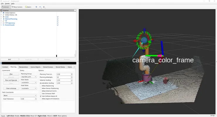
圖 14:將從校準(zhǔn)中獲得的值設(shè)置為 TF 并廣播它并不完美,但我能夠?qū)⑵畋3衷诳山邮艿姆秶鷥?nèi),以便簡單地到達(dá)并拾取物體。
當(dāng)移動點(diǎn)云和疊加的機(jī)器人模型時(shí),您可以看到這一點(diǎn)。
myCobot的關(guān)節(jié)有一點(diǎn)間隙,這使得很難做出精確的動作。
由于從實(shí)感獲得的點(diǎn)云坐標(biāo)系被轉(zhuǎn)換為myCobot的坐標(biāo)系,因此我們嘗試將myCobot的尖端定位為對象。(我試圖使用 MoveIt 訪問它,但它被困在C++,所以我制作了一個(gè)可以使用 pymycobot 輕松操作的腳本)
由于坐標(biāo)位于相機(jī)的光學(xué)坐標(biāo)系中,因此請使用先前獲得的平移和旋轉(zhuǎn)將它們轉(zhuǎn)換為myCobot坐標(biāo)系。將以下內(nèi)容添加到腳本目錄。
# mycobot_reaching.py#!/usr/bin/env python3 import time, os, sys import numpy as np import quaternion from pymycobot.mycobot import MyCobot import rospy from geometry_msgs.msg import Point from tf.transformations import quaternion_from_euler class MyCobotReachingNode(object): def __init__(self): super(MyCobotReachingNode, self).__init__() rospy.init_node("mycobot_reaching_node") rospy.loginfo("mycobot reaching start") # メンバ変數(shù) # mycobot インスタンス # member variable # mycobot instance port = "/dev/ttyUSB0" self.mycobot = MyCobot(port, baudrate="115200", timeout=0.1, debug=False) # 平行移動と回転 # 光學(xué)座標(biāo)系→mycoboto座標(biāo)系なので4.2節(jié)とXYZ軸が違うことに注意 # Translation and rotation # Note that the XYZ axes are different from those in section 4.2 because the optical coordinate system is a mycoboto coordinate system self.translation_from_camera_to_mycobot = np.array([t_x, t_y, t_z]) q = quaternion_from_euler(-theta_2, -theta_3, theta_1) self.rotation_from_camera_to_mycobot = quaternion.as_quat_array(q) # subscriber self.sub_point() # Subscriber def sub_point(self): def callback(data): rospy.loginfo("subscribed target point") self.mycobot_move(data) sub = rospy.Subscriber("object_position", Point, callback = callback) rospy.spin() # move mycobot def mycobot_move(self, point_data): # mycobot座標(biāo)系への変換 # Convert to mycobot coordinate system target_point = np.array([point_data.x, point_data.y, point_data.z]) target_point -= self.translation_from_camera_to_mycobot target_point = quaternion.rotate_vectors(self.rotation_from_camera_to_mycobot, target_point) # mm単位のため*1000、手前中心付近にリーチングするためx-20mm, z+40mm # *1000 for mm increments, x-20mm, z+40mm for reaching around the center of the front coord_list = [target_point[0]*1000-20, -target_point[2]*1000, target_point[1]*1000+40, 0, 90, 0] self.mycobot.send_coords(coord_list, 70, 0) time.sleep(1.5) if __name__ == "__main__": reaching = MyCobotReachingNode() pass
這一次,我將調(diào)動我使用過的所有庫和我制作的腳本。
您可以在 6 個(gè)終端中運(yùn)行 rs_camera.launch、mycobot_moveit_control.launch、tf_broadcaster、red_point_detection.py、object_position_search.py、mycobot_reaching.py,但每次打開終端時(shí),您都必須對其進(jìn)行設(shè)置......調(diào)試會很困難,因此請創(chuàng)建自己的啟動文件。
轉(zhuǎn)到工作區(qū),創(chuàng)建用于啟動的目錄和文件,并將啟動路徑添加到 CMakeLists.txt。
$ cd /src/mycobot_test$ mkdir launch$ cd launch$ touch mycobot_reaching.launch # CMakeLists.txt~~# Add launch fileinstall(FILES DESTINATION ${CATKIN_PACKAGE_SHARE_DESTINATION}/launch ) ~~
啟動文件的結(jié)構(gòu)很簡單,只需將要同時(shí)運(yùn)行的節(jié)點(diǎn)和啟動文件中的啟動文件排列在啟動選項(xiàng)卡中即可。要執(zhí)行節(jié)點(diǎn),請?jiān)诠?jié)點(diǎn)標(biāo)記中寫入任何節(jié)點(diǎn)名稱,并像 rosrun 一樣寫入包名稱和可執(zhí)行文件名稱。添加輸出=“屏幕”,如果您希望輸出顯示在命令行上。
在引導(dǎo)文件中執(zhí)行啟動時(shí),在包含標(biāo)記中包含文件路徑。嘗試catkin_make并運(yùn)行它。
$ roslaunch mycobot_test mycobot_reaching.launch
我能夠移動myCobot來跟蹤RealSense捕獲的紅色物體,就像在電影1中一樣。
跟著項(xiàng)目跟著做之前有很多滯后,總覺得自己在各方面都學(xué)得還不夠。
7. 總結(jié)
在本文中,我總結(jié)了如何使用 ROS 來協(xié)調(diào) 6 軸機(jī)械臂 myCobot 和深度攝像頭實(shí)感 D455。我沒有機(jī)器人開發(fā)的經(jīng)驗(yàn),包括ROS。我認(rèn)為沒有一個(gè)博客總結(jié)了我到目前為止從頭開始嘗試的內(nèi)容,所以如果你買了一個(gè)機(jī)械臂或深度相機(jī)但不知道如何使用它,我希望它對那些想知道如何使用它的人有所幫助。另外,如果具有機(jī)器人開發(fā)經(jīng)驗(yàn)或擅長數(shù)據(jù)處理的人可以指出最好做這樣的事情,我將不勝感激。
這次我將我在模擬器中學(xué)到的強(qiáng)化學(xué)習(xí)模型應(yīng)用于myCobot,并進(jìn)行了拾取實(shí)驗(yàn),所以我可能會寫另一篇博客作為第2部分。
參考
1. 松林達(dá)志, 2022.12.21, 實(shí)感D455による空間認(rèn)識でmyCobotを操作.
2. 阿爾伯特公司
審核編輯黃宇
-
傳感器
+關(guān)注
關(guān)注
2565文章
52954瀏覽量
767056 -
機(jī)器人
+關(guān)注
關(guān)注
213文章
29718瀏覽量
212769 -
攝像頭
+關(guān)注
關(guān)注
61文章
4976瀏覽量
98316 -
大象機(jī)器人
+關(guān)注
關(guān)注
0文章
86瀏覽量
120
發(fā)布評論請先 登錄
使用myCobot 280 Jeston Nano進(jìn)行物體精確識別追蹤
試用 Intel RealSense
如何將D435 realsense連接到intel aero現(xiàn)有的RealSense R200引腳
受磁鐵影響的RealSense D415/D435?
哪個(gè)實(shí)際相機(jī)在2到5米范圍內(nèi)具有最佳的深度感知和物體識別平衡?
怎么將RealSense D415包文件轉(zhuǎn)換為PCD
Q455C/D/F閥門聯(lián)動裝置用戶手冊
英特爾將IMU搭載到RealSense攝像頭D435i系統(tǒng)中
RealSense400系列相機(jī)介紹和使用實(shí)踐資料免費(fèi)下載
英特爾RealSense D455發(fā)布,拍攝范圍對上一代產(chǎn)品增大一倍
英特爾RealSense ID結(jié)合了深度傳感器與人臉識別系統(tǒng)
Intel推出全新3D人臉識別模組,能為智能門鎖等應(yīng)用場景提供技術(shù)支持
英特爾發(fā)布了RealSense ID 開發(fā)了一種面部識別系統(tǒng)
英特爾推出基于RealSense技術(shù)的3D人臉驗(yàn)證解決方案
MAX6394US455D3+T PMIC - 監(jiān)控器


 工商網(wǎng)監(jiān)
評論