 如何使用Arduino和LED實現隨機性

步驟1:您需要的內容。
您將需要:
6個LED(可能還有更多)。
跳線
面包板和/或原型板
第2步:編程。
使用以下代碼對Arduino進行編程。
//feel free to make changes
//do not connect led‘s in sequential order
//make sure all led’s are connected to a resistor if applicable
//this project was made and tested using only one wire and arduino‘s pin 13 resistor and LED
//note: pin 5 and 6 act weird in the beginning - an arduino bug
byte led1 = 3;
byte led2 = 5;
byte led3 = 6;
byte led4 = 9;
byte led5 = 10;
byte led6 = 11;
int x = 0;
int y = 0;
int steps = 1; //change if needed, defines the steps between 0 and 255, a lower number is smoother
//make sure the variable “steps” is a factor of 255; any of the below numbers
//factors of 255 are : 1,3,5,15,17,51,85,255
//sorry for a lot of notes, but remember to change variable “delaytime” according to variable “steps”
//delay is in milliseconds for below
int delaytime = 10; //change if needed, delay between increments of PWM
//850 milliseconds is on-off/off-on time, in 17 step increments of brightness
int delaytime2 = 1000; //change if needed, delay between switching of leds
void setup (){
pinMode (led1, OUTPUT);
pinMode (led2, OUTPUT);
pinMode (led3, OUTPUT);
pinMode (led4, OUTPUT);
pinMode (led5, OUTPUT);
pinMode (led6, OUTPUT);
do {
x = x + steps;
analogWrite (led1, x);
analogWrite (led2, x);
delay (delaytime);
}
while (x != 255);
}
void loop (){
y = 0;
x = 255;
delay (delaytime);
do{
y = y + steps;
x = x - steps;
analogWrite (led3, y);
analogWrite (led1, x);
delay (delaytime);
}
while (y != 255 && x != 0);
delay (delaytime2);
y = 0;
x = 255;
do{
y = y + steps;
x = x - steps;
analogWrite (led4, y);
analogWrite (led2, x);
delay (delaytime);
}
while (y != 255 && x != 0);
delay (delaytime2);
y = 0;
x = 255;
do{
y = y + steps;
x = x - steps;
analogWrite (led5, y);
analogWrite (led3, x);
delay (delaytime);
}
while (y != 255 && x != 0);
delay (delaytime2);
y = 0;
x = 255;
do{
y = y + steps;
x = x - steps;
analogWrite (led6, y);
analogWrite (led4, x);
delay (delaytime);
}
while (y != 255 && x != 0);
delay (delaytime2);
y = 0;
x = 255;
do{
y = y + steps;
x = x - steps;
analogWrite (led1, y);
analogWrite (led5, x);
delay (delaytime);
}
while (y != 255 && x != 0);
delay (delaytime2);
y = 0;
x = 255;
do{
y = y + steps;
x = x - steps;
analogWrite (led2, y);
analogWrite (led6, x);
delay (delaytime);
}
while (y != 255 && x != 0);
delay (delaytime2);
}
第3步:電路。
每個LED并將其連接到面包板的接地導軌。將正極引線連接到Arduino的引腳3、5、6、9、10、11。
步驟4:漸隱!
現在,LED應該以偽隨機的方式褪色。您已完成,但對于印象深刻的人,請單擊“下一步”。
步驟5:下沉和采購。
這是我如何教授下沉和源的方法。
下沉是指從輸出引腳到地。所謂采購,是指從正極到輸出引腳。
這樣想。電源可以從LED流向源極。在下沉時,電源來自引腳。電源始終由引腳提供,因此,當引腳變為高電平時,電流會“通過” LED到達引腳,從而將其關閉。
對于大多數人來說,他們應該說:“這有什么區別? “
對一個隨機的人moi來說,它的意思是:“我可以反轉信號,從而產生更大的隨機性!”
請記住,避免使用電阻器(有生命危險)從3.3伏特為其供電。 p》
第6步:這樣做。..
現在取第3針作為源。
取第6針作為源。
取第9針作為源。
然后取第11針作為源。
將其余的留在原處。
第7步:確實完成。
現在,可以實現隨機效果(讓我惡作劇的時間)(借口) -moi 。.. BWA-HA-HAHA-HA!)點擊完成。
-
led
+關注
關注
242文章
23828瀏覽量
673782 -
Arduino
+關注
關注
190文章
6498瀏覽量
192037
發布評論請先 登錄
藍牙隨機化RPA更新的重要性和工作原理
一種采用NMOS濾出開關電源輸出紋波的電路
關于LED燈具的9種可靠性測試方案
隨機化在PCIe IDE驗證中的重要性

AI的“隨機性”挑戰:它們比人類更“不隨機”?

如何使用Arduino實現CAN總線通信呢
ADC12DJ3200采樣數據在FPGA端隨機性出現錯點,是什么原因?
如何使用Arduino實現CAN總線通信
淺談分布式電源和電動汽車的配電網可靠性評估

TLV320DAC3101讀寫寄存器不穩定是怎么回事?如何解決?
閃存隨機讀寫與連續讀寫哪個重要
快速啟停!AEM在新能源制綠氫應用中的適配性。

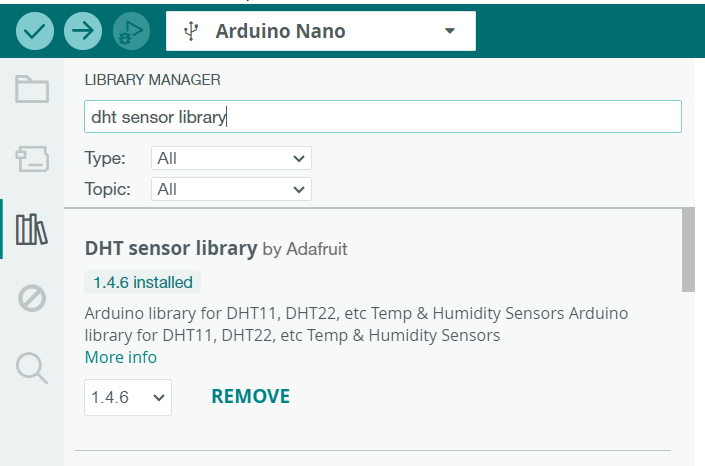
Arduino Nano 和 DHT11 實現 LabVIEW 溫濕度采集
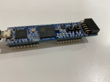
arduino(1)--ESP8266配置
如何在FPGA中實現隨機數發生器


 工商網監
工商網監
評論