 Arduino實時時鐘的制作圖解
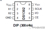
步驟1:關于DS 1307


簡介:
除了arduino,DS1307集成電路是該項目的核心因為它充當計時器,并告知arduino什么時候應該將設備保持打開狀態。 DS 1307專為計時而設計,時間相當準確,每個月大約有1分鐘的錯誤(時間漂移)。如果您想消除這種情況,您可以選擇DS3234,它的時間漂移僅為每年1分鐘。對于我們的特定應用,我們可以選擇DS1307本身。
DS1307的優點在于它具有備用的紐扣電池。該紐扣電池通常為CR2032。這種電池對于IC來說綽綽有余,因為DS1307的功耗非常低,因此該電池的備用電池壽命至少約為9年。
因此,現在討論這些規格讓我們談談交流。 DS 1307使用I2C通信與arduino通信。只需將芯片以十進制形式發送數據,使得每個十進制形式都是4位二進制數據,也稱為二進制編碼十進制系統。
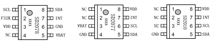
重要引腳:
5V引腳: :當該引腳為高電平時,ds1307發送數據,為低電平時,它在備份按鈕單元上運行。
GND: 這是模塊的接地引腳。電池的接地和電源都連接在一起。
SDA: 這是i2c數據引腳-與RTC進行通信。
現在,介紹已經完成。讓我們開始實際制作模塊。該指導書包含焊接步驟以及板上組件的放置位置。希望這種方法比僅僅提供電路圖更好理解。
步驟2:組裝和焊接-1
因此該模塊只有2 x 3 cm的尺寸,非常緊湊。該模塊具有電線連接器,但您也可以使用公頭或母頭接頭,以便將其直接插入Arduino。無論如何,除了不焊接方波引腳之外,模塊都具有所有功能。
制造模塊:
步驟1:
將原型板切成上述尺寸,然后插入幣形電池座。然后焊接底端以將電池固定在其位置。
第2步:
將DIP插座插入下一步固定到晶胞支架上,但如圖所示,為晶振留出了空間。焊接一些引腳以將插座固定到位。
第3步:
現在將晶體振蕩器插入第一個晶體振蕩器附近。 DIP插座的第二個針腳,如圖所示。然后如圖所示進行焊接。
注意1:
此注釋用于顯示我的4針連接器的顏色代碼僅供參考,因為您的顏色可能有所不同,請仔細檢查是否已正確連接。
注2: p》
現在,我們需要使用如圖所示的走線連接電池端子。這些連接提供備用電源。
步驟3:組裝和焊接-2
第5步:
現在插入來自Arduino的電源引腳。正引腳連接到DS 1307的第八引腳。然后,IC和紐扣單元的接地是公共的。
步驟6:
在這一步中,我們連接來自Arduino的其他兩個數據引腳,如圖所示。很抱歉,因為我將模塊做得很小,所以10k電阻沒有孔。我將電阻器和導線都插入了相同的引腳,然后進行了焊接。
第7步:
因此,接下來插入電線,我們需要在兩個引腳中分別插入10k電阻。兩個電阻的另一端連接到DS 1307的電源引腳8。然后將導線焊接起來,以供參考。
步驟8:
由于我在此模塊中使用了連接器,因此頻繁使用會導致電線磨損。所以我用電阻器上的電線剪了一下。首先將電線插入一端并焊接以使其堅固。然后制作一個U形彎頭,并使電線穿過該U形彎頭,并擰緊U形彎頭以獲得良好的抓地力,然后再焊接另一端以形成接頭。該圖比文字更能說明該方法。
該模塊最終完成,因此將電池和DS1307 IC都插入其插槽中。最終圖顯示了完整完整的模塊。
步驟4:檢查和設置模塊


組裝完模塊后。將模塊連接到Arduino,以便將引腳正確插入Arduino。下面給出了測試模塊的程序。代碼會不斷通過串行端口更新時間。
為了運行模塊,我們需要兩個庫,而在Arduino軟件中則需要兩個庫。以下步驟使用所需的庫和代碼來設置Arduino軟件。
導入庫:
下載庫“ RealTimeClockDS1307 ”并將其保存在桌面中。
打開Arduino,然后轉到素描 =》 導入庫 =》 添加庫。
然后選擇保存在桌面中的庫,然后單擊添加。
現在粘貼下面給出的示例代碼,然后點擊編譯。如果編譯成功,則跳過其余步驟。
如果沒有導入第二個庫“ Wire ”,重復相同的過程并編譯代碼,它將起作用。
代碼正常工作:
代碼是由“ David H. Brown”編寫的,我只是用它來給你DS1307的簡介。無論如何,Arduino與RTC模塊通信并通過 Serial Monitor 每秒更新一次時間。創建者為我們提供了一個選項,用于設置發送命令“ ?”的時間。出現以下菜單。
Try these:
h## - set Hours [range 1..12 or 0..24]
i## - set mInutes [range 0..59]
s## - set Seconds [range 0..59]
d## - set Date [range 1..31]
m## - set Month [range 1..12]
y## - set Year [range 0..99]
w## - set arbitrary day of Week [range 1..7]
t - toggle 24-hour mode
a - set AM p - set PM
z - start clock Z - stop clock
q - SQW/OUT = 1Hz Q - stop SQW/OUT
該代碼將幫助您設置時間以及檢查模塊的備用電池供電是否正常。在下一個教程中,我將向您展示如何設置LCD顯示器并顯示RTC模塊中的時間。這是用于測試模塊及其附件的代碼。
#include
#include
//RealTimeClock RTC;//=new RealTimeClock();
#define Display_Clock_Every_N_Seconds 10 // n.secs to show date/time
#define Display_ShortHelp_Every_N_Seconds 60 // n.secs to show hint for help
//#define TEST_Squarewave
//#define TEST_StopStart
//#define TEST_1224Switch
int count=0;
char formatted[] = “00-00-00 00:00:00x”;
void setup() {
// Wire.begin();
Serial.begin(9600);
pinMode(A3, OUTPUT); //*** pin 16 (Analog pin 2) as OUTPUT ***
digitalWrite(A3, HIGH); //*** pin 16 (Analog pin 2) set to LOW ***
pinMode(A2, OUTPUT); //*** pin 17 (Analog pin 3) as OUTPUT ***
digitalWrite(A2, LOW); //*** pin 17 (Analog pin 3) set to HIGH ***
//*** Analog Pin settings to power RTC module ***
}
void loop() {
if(Serial.available())
{
processCommand();
}
RTC.readClock();
count++;
if(count % Display_Clock_Every_N_Seconds == 0){
Serial.print(count);
Serial.print(“: ”);
RTC.getFormatted(formatted);
Serial.print(formatted);
Serial.println();
}
if(count % Display_ShortHelp_Every_N_Seconds == 0) {
Serial.println(“Send ? for a list of commands.”);
}
#ifdef TEST_Squarewave
if(count%10 == 0)
{
switch(count/10 % 6)
{
case 0:
Serial.print(“Squarewave disabled (low impedance): ”);
RTC.sqwDisable(0);
Serial.println((int) RTC.readData(7));
break;
case 1:
Serial.print(“Squarewave disabled (high impedance): ”);
RTC.sqwDisable(1);
Serial.println((int) RTC.readData(7));
break;
case 2:
Serial.println(“Squarewave enabled at 1 Hz”);
RTC.sqwEnable(RTC.SQW_1Hz);
break;
case 3:
Serial.println(“Squarewave enabled at 4.096 kHz”);
RTC.sqwEnable(RTC.SQW_4kHz);
break;
case 4:
Serial.println(“Squarewave enabled at 8.192 kHz”);
RTC.sqwEnable(RTC.SQW_8kHz);
break;
case 5:
Serial.println(“Squarewave enabled at 32.768 kHz”);
RTC.sqwEnable(RTC.SQW_32kHz);
break;
default:
Serial.println(“Squarewave test not defined”);
}//switch
}
#endif
#ifdef TEST_StopStart
if(count%10 == 0)
{
if(!RTC.isStopped())
{
if(RTC.getSeconds() 《 45)
{
Serial.println(“Stopping clock for 10 seconds”);
RTC.stop();
}//if we have enough time
} else {
RTC.setSeconds(RTC.getSeconds()+11);
RTC.start();
Serial.println(“Adding 11 seconds and restarting clock”);
}
}//if on a multiple of 10 counts
#endif
#ifdef TEST_1224Switch
if(count%10 == 0)
{
if(count %20 == 0)
{
Serial.println(“switching to 12-hour time”);
RTC.switchTo12h();
RTC.setClock();
}
else
{
Serial.println(“switching to 24-hour time”);
RTC.switchTo24h();
RTC.setClock();
}
}
#endif
}
void processCommand() {
if(!Serial.available()) { return; }
char command = Serial.read();
int in,in2;
switch(command)
{
case ‘H’:
case ‘h’:
in=SerialReadPosInt();
RTC.setHours(in);
RTC.setClock();
Serial.print(“Setting hours to ”);
Serial.println(in);
break;
case ‘I’:
case ‘i’:
in=SerialReadPosInt();
RTC.setMinutes(in);
RTC.setClock();
Serial.print(“Setting minutes to ”);
Serial.println(in);
break;
case ‘S’:
case ‘s’:
in=SerialReadPosInt();
RTC.setSeconds(in);
RTC.setClock();
Serial.print(“Setting seconds to ”);
Serial.println(in);
break;
case ‘Y’:
case ‘y’:
in=SerialReadPosInt();
RTC.setYear(in);
RTC.setClock();
Serial.print(“Setting year to ”);
Serial.println(in);
break;
case ‘M’:
case ‘m’:
in=SerialReadPosInt();
RTC.setMonth(in);
RTC.setClock();
Serial.print(“Setting month to ”);
Serial.println(in);
break;
case ‘D’:
case ‘d’:
in=SerialReadPosInt();
RTC.setDate(in);
RTC.setClock();
Serial.print(“Setting date to ”);
Serial.println(in);
break;
case ‘W’:
Serial.print(“Day of week is ”);
Serial.println((int) RTC.getDayOfWeek());
break;
case ‘w’:
in=SerialReadPosInt();
RTC.setDayOfWeek(in);
RTC.setClock();
Serial.print(“Setting day of week to ”);
Serial.println(in);
break;
case ‘t’:
case ‘T’:
if(RTC.is12hour()) {
RTC.switchTo24h();
Serial.println(“Switching to 24-hour clock.”);
} else {
RTC.switchTo12h();
Serial.println(“Switching to 12-hour clock.”);
}
RTC.setClock();
break;
case ‘A’:
case ‘a’:
if(RTC.is12hour()) {
RTC.setAM();
RTC.setClock();
Serial.println(“Set AM.”);
} else {
Serial.println(“(Set hours only in 24-hour mode.)”);
}
break;
case ‘P’:
case ‘p’:
if(RTC.is12hour()) {
RTC.setPM();
RTC.setClock();
Serial.println(“Set PM.”);
} else {
Serial.println(“(Set hours only in 24-hour mode.)”);
}
break;
case ‘q’:
RTC.sqwEnable(RTC.SQW_1Hz);
Serial.println(“Square wave output set to 1Hz”);
break;
case ‘Q’:
RTC.sqwDisable(0);
Serial.println(“Square wave output disabled (low)”);
break;
case ‘z’:
RTC.start();
Serial.println(“Clock oscillator started.”);
break;
case ‘Z’:
RTC.stop();
Serial.println(“Clock oscillator stopped.”);
break;
case ‘》’:
in=SerialReadPosInt();
in2=SerialReadPosInt();
RTC.writeData(in, in2);
Serial.print(“Write to register ”);
Serial.print(in);
Serial.print(“ the value ”);
Serial.println(in2);
break;
case ‘《’:
in=SerialReadPosInt();
in2=RTC.readData(in);
Serial.print(“Read from register ”);
Serial.print(in);
Serial.print(“ the value ”);
Serial.println(in2);
break;
default:
Serial.println(“Unknown command. Try these:”);
Serial.println(“ h## - set Hours [range 1..12 or 0..24]”);
Serial.println(“ i## - set mInutes [range 0..59]”);
Serial.println(“ s## - set Seconds [range 0..59]”);
Serial.println(“ d## - set Date [range 1..31]”);
Serial.println(“ m## - set Month [range 1..12]”);
Serial.println(“ y## - set Year [range 0..99]”);
Serial.println(“ w## - set arbitrary day of Week [range 1..7]”);
Serial.println(“ t - toggle 24-hour mode”);
Serial.println(“ a - set AM p - set PM”);
Serial.println();
Serial.println(“ z - start clock Z - stop clock”);
Serial.println(“ q - SQW/OUT = 1Hz Q - stop SQW/OUT”);
Serial.println();
Serial.println(“ 》##,### - write to register ## the value ###”);
Serial.println(“ 《## - read the value in register ##”);
}//switch on command
}
//read in numeric characters until something else
//or no more data is available on serial.
int SerialReadPosInt() {
int i = 0;
boolean done=false;
while(Serial.available() && !done)
{
char c = Serial.read();
if (c 》= ‘0’ && c 《=‘9’)
{
i = i * 10 + (c-‘0’);
}
else
{
done = true;
}
}
return i;
}
步驟5:關于庫
開始之前在液晶顯示屏上顯示時間。我想討論一下我們導入的庫。我省略了需要方波數據的庫,因為該模塊沒有方波輸出引腳。讓我們通過一些示例來討論該庫中涉及的各種關鍵字。
關鍵字:
起始時鐘:
RTC.start();
此時鐘可用于啟動時鐘,它將從停止時開始計時。首次使用該模塊以啟動模塊時,應使用此命令。
停止時鐘:
RTC.stop();
使用此行,可以暫停該模塊,并且在給出啟動命令之前,時鐘不會計時。它與開始時鐘命令一起使用以控制模塊的狀態。
讀取時鐘:
RTC.readClock();
使用“開始”命令打開時鐘后。您需要從RTC模塊讀取數據。這是通過readClock函數完成的。在使用后面的命令之前,此功能必不可少。
讀取時間:
//integers for holding the various time values.
int hours = 0;
int minutes = 0;
int seconds = 0;
int dates = 0;
int months = 0;
int years = 0;
int date = 0;
//syntax for setting the values to the integers
RTC.readClock(); //This line is essential for the other commands to work.
//Commands for getting the individual time values.
hours = RTC.getHours();
minutes = RTC.getMinutes();
seconds = RTC.getSeconds();
dates = RTC.getDate();
months = RTC.getMonth();
years = RTC.getYear();
date = RTC.getDayofWeek();
//finally just print the stored data (refer next step)。
因此一旦readClock被調用。接下來,我們需要將各個值存儲為整數。我們創建整數來保存值。 getDayofWeek函數提供星期幾。第一天為星期一,最后一天為星期日。請注意,與前面步驟中的代碼相比,此方法效率很低,但這將有助于您了解庫中各種功能的工作。
注意:
//extra code for finding out whether its AM or PM when the clock is in 12h mode.
//declare an integer and string.
int AP = 0;
String TZ;
//then read the data from the module.
ampm = RTC.isPM();
//use an if loop to find out whether its AM or PM.
if(ampm == 1)
{
am = “PM”;
}
else
{
am =“AM”;
}
此額外的代碼行將在12小時模式下顯示其上午還是下午。當您將其設置為24小時制時,請刪除此代碼。
寫時間:
RTC.setHours(4);
RTC.setMinutes(35);
RTC.setSeconds(14);
RTC.setDate(9);
RTC.setMonth(6);
RTC.setYear(14);
RTC.set24h();
//RTC.setAM();
RTC.setPM();
RTC.setDayofWeek(1);
因此,這些是用于設置模塊時間的命令。如您所見,我已經設置了 4:35:14 PM 的時間,日期為 9/6/14 。除了這些命令外,還有set24h命令,直接將時鐘設置為24小時模式,并將AM和PM設置為12小時模式。 setDayofWeek用于設置日期。
時間命令:
//These commands deal with the settings in the module.
//Checks whether the clock is running.
RTC.isStopped();
//Check whether it is AM or PM depending on the output(given above)。
RTC.isPM();
//Checks whether the clock is in 24hour mode.
RTC.is12hour();
//Toggles between the 12hour mode and 24hour mode.
RTC.switchTo24h();
以下是這些命令:控制時鐘內的設置。
我已經盡我所能解釋了這個庫。如果發現任何缺陷或我錯過的東西,請對其進行評論,以使其盡可能準確。
步驟6:顯示時間(簡單方法)

現在檢查了模塊,現在讓我們開始獲取要在LCD上顯示的時間數據。 LCD模塊可以輕松連接到Arduino。顯示了用于連接LCD模塊的電路圖。下面顯示了用于顯示時間的代碼。
在我制作了此代碼的兩個版本之前。其中一個將普通LCD連接到Arduino。這是最簡單的版本,但是它將占用Arduino中的大多數引腳。因此,我想出了一個替代方案,使用移位寄存器僅使用2個引腳將數據發送到LCD模塊。因此,您可以選擇更方便的方式。
普通版:
更多的引腳,但是更簡單!
因此,如面包板圖所示,連接LCD。然后將代碼上傳到Arduino,日期和時間將顯示在LCD顯示屏中。因此,這是代碼。
代碼:
#include
#include
#include
LiquidCrystal lcd(12, 11, 5, 4, 3, 2);
#define Display_Clock_Every_N_Seconds 10
#define Display_ShortHelp_Every_N_Seconds 60
String tz;
int hours = 0;
int minutes = 0;
int seconds = 0;
int dates = 0;
int months = 0;
int years = 0;
int ap = 0;
void setup() {
Serial.begin(9600);
lcd.begin(16,2);
pinMode(A3, OUTPUT);
digitalWrite(A3, HIGH);
pinMode(A2, OUTPUT);
digitalWrite(A2, LOW);
}
void loop() {
RTC.readClock();
if(ap == 1)
{
tz = “PM”;
}
else
{
tz =“AM”;
}
lcd.home();
hours = RTC.getHours();
minutes = RTC.getMinutes();
seconds = RTC.getSeconds();
ap = RTC.isPM();
dates = RTC.getDate();
months = RTC.getMonth();
years = RTC.getYear();
lcd.print(hours);
lcd.print(“:”);
lcd.print(minutes);
lcd.print(“:”);
lcd.print(seconds);
lcd.print(“ ”);
lcd.print(tz);
lcd.setCursor(0, 1);
lcd.print(dates);
lcd.print(“:”);
lcd.print(months);
lcd.print(“:”);
lcd.print(years);
delay(250);
lcd.clear();
lcd.home();
lcd.print(hours);
lcd.print(“ ”);
lcd.print(minutes);
lcd.print(“ ”);
lcd.print(seconds);
lcd.print(“ ”);
lcd.print(tz);
lcd.setCursor(0, 1);
lcd.print(dates);
lcd.print(“ ”);
lcd.print(months);
lcd.print(“ ”);
lcd.print(years);
delay(250);
lcd.clear();
}
在連接RTC模塊并上傳代碼后。液晶顯示屏將在頂部顯示時間,在底部顯示日期。此版本對于學習基本命令很有用,并允許您在將來的項目中使用這些命令。
步驟7:顯示時間(移位寄存器版本)

移位寄存器LCD版本:
此版本使用的移位寄存器模塊僅使用兩個就可以將數據發送到LCD引腳而不是六個引腳。可以購買此模塊,但我想制造它。即將發布的鏈接中提供了制作模塊的完整說明!因此,只需將Arduino的兩個引腳連接到模塊,然后上傳下面給出的代碼,就可以像在簡單版本中一樣觀察到相同的輸出。
CODE:
#include
#include
#include
LiquidCrystal_SR lcd(8,7,TWO_WIRE);
#define Display_Clock_Every_N_Seconds 10
#define Display_ShortHelp_Every_N_Seconds 60
String tz;
int hours = 0;
int minutes = 0;
int seconds = 0;
int dates = 0;
int months = 0;
int years = 0;
int ap = 0;
void setup() {
// Wire.begin();
Serial.begin(9600);
lcd.begin(16,2);
pinMode(A3, OUTPUT);
digitalWrite(A3, HIGH);
pinMode(A2, OUTPUT);
digitalWrite(A2, LOW);
}
void loop() {
RTC.readClock();
ap = RTC.isPM();
if(ap == 1)
{
tz = “PM”;
}
else
{
tz =“AM”;
}
lcd.home();
hours = RTC.getHours();
minutes = RTC.getMinutes();
seconds = RTC.getSeconds();
dates = RTC.getDate();
months = RTC.getMonth();
years = RTC.getYear();
lcd.print(hours);
lcd.print(“:”);
lcd.print(minutes);
lcd.print(“:”);
lcd.print(seconds);
lcd.print(“ ”);
lcd.print(tz);
lcd.setCursor(0, 1);
lcd.print(dates);
lcd.print(“:”);
lcd.print(months);
lcd.print(“:”);
lcd.print(years);
delay(250);
lcd.clear();
lcd.home();
lcd.print(hours);
lcd.print(“ ”);
lcd.print(minutes);
lcd.print(“ ”);
lcd.print(seconds);
lcd.print(“ ”);
lcd.print(tz);
lcd.setCursor(0, 1);
lcd.print(dates);
lcd.print(“ ”);
lcd.print(months);
lcd.print(“ ”);
lcd.print(years);
delay(250);
lcd.clear();
}
如果您已經有了此模塊,則第二個代碼使用另一個庫,請使用該庫使上面的代碼正常工作。
-
時鐘
+關注
關注
11文章
1878瀏覽量
132807 -
Arduino
+關注
關注
188文章
6489瀏覽量
190029
發布評論請先 登錄
愛普生RA4000CE實時時鐘模塊車載BMS系統的理想選擇

實時時鐘模塊選擇指南和比較表
基于FPGA的實時時鐘設計

適用于智能門鎖的低功耗RTC實時時鐘模塊RX8010SJ

TCXO RTC實時時鐘模塊的特性


 工商網監
工商網監
評論