") RT-Thread記錄(十三、I/O 設(shè)備模型之PIN設(shè)備)
RT-Thread記錄(十三、I/O 設(shè)備模型之PIN設(shè)備)
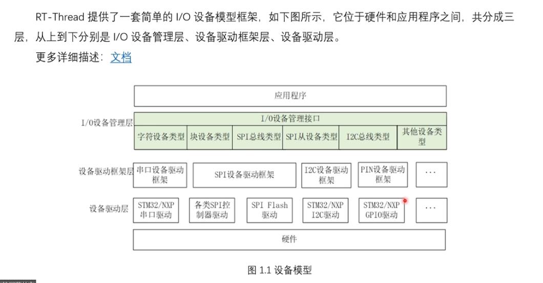
講完UART設(shè)備之后,我們已經(jīng)熟悉RT-Thread I/O 設(shè)備模型了,回頭看看基本的 PIN 設(shè)備。
目錄
前言
一、PIN 設(shè)備模型解析
1.1 初識(shí) GPIO 操作函數(shù)
1.2 PIN 設(shè)備框架
1.3 PIN 設(shè)備驅(qū)動(dòng)框架層
實(shí)現(xiàn)的函數(shù)
PIN 設(shè)備控制塊
注冊(cè)函數(shù)
1.4 PIN 設(shè)備驅(qū)動(dòng)層
實(shí)現(xiàn)的函數(shù)
初始化函數(shù)
☆引腳定義☆
二、PIN 設(shè)備操作函數(shù)
2.1 獲取 PIN 索引號(hào)方法
2.2 操作函數(shù)
2.2.1 設(shè)置 GPIO 模式
2.2.2 設(shè)置/ 讀取 GPIO 電平
2.2.3 綁定/脫離中斷回調(diào)函數(shù)
2.2.4 使能中斷
三、PIN 設(shè)備示例
結(jié)語(yǔ)
前言
我們學(xué)習(xí)一個(gè) MCU 的最基本的 GPIO 口,也就是 PIN 設(shè)備模型,我們還沒有講過(guò),至于原因之前也說(shuō)了,因?yàn)?PIN 設(shè)備的操作函數(shù)與我們介紹的 I/O 設(shè)備模型的通用函數(shù)名稱不太對(duì)應(yīng),對(duì)于新手來(lái)說(shuō)先將 PIN 設(shè)備可能會(huì)讓人難以理解。
所以前面的文章我們先講了 UART 設(shè)備模型,從源碼分析了一下 UART 設(shè)備的設(shè)計(jì)思路,從設(shè)備驅(qū)動(dòng)層,和設(shè)備驅(qū)動(dòng)框架層再到 I/O 設(shè)備管理層,最后到應(yīng)用層,我們都理過(guò)一遍。
有了前面的經(jīng)驗(yàn),本文我們就來(lái)學(xué)習(xí)了解 RT-Thread PIN設(shè)備 。
??
本 RT-Thread 專欄記錄的開發(fā)環(huán)境:
RT-Thread記錄(一、RT-Thread 版本、RT-Thread Studio開發(fā)環(huán)境 及 配合CubeMX開發(fā)快速上手)
RT-Thread記錄(二、RT-Thread內(nèi)核啟動(dòng)流程 — 啟動(dòng)文件和源碼分析)
??
RT-Thread 設(shè)備篇系列博文鏈接:
RT-Thread記錄(十、全面認(rèn)識(shí) RT-Thread I/O 設(shè)備模型)
RT-Thread記錄(十一、I/O 設(shè)備模型之UART設(shè)備 — 源碼解析)
RT-Thread記錄(十二、I/O 設(shè)備模型之UART設(shè)備 — 使用測(cè)試)
一、PIN 設(shè)備模型解析
一直說(shuō)到 PIN 設(shè)備有點(diǎn)特殊,和我們講 I/O 設(shè)備模型時(shí)候的設(shè)備感覺有一點(diǎn)區(qū)別的,那么到底怎么個(gè)特殊法?我們還是需要具體來(lái)分析一下:
1.1 初識(shí) GPIO 操作函數(shù)
我們還是從上層的 I/O 設(shè)備管理層來(lái)開始,看看 PIN 設(shè)備管理層提供的訪問(wèn) GPIO 的接口有哪些:
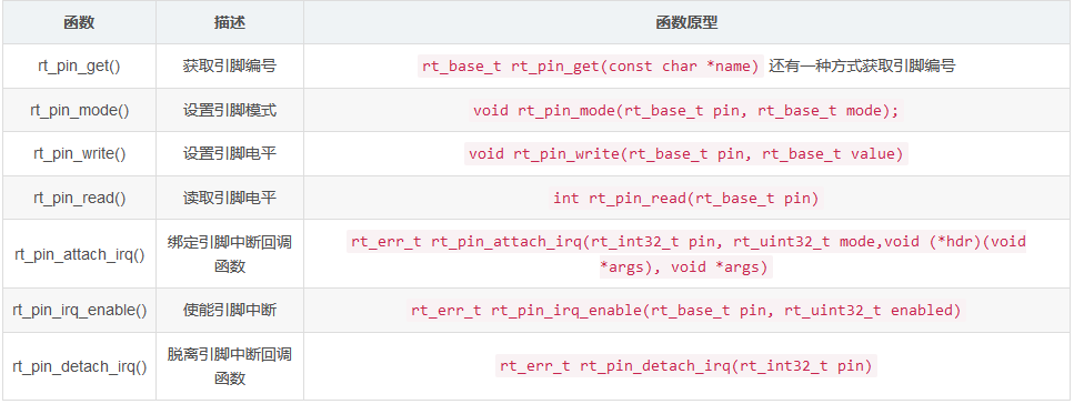
我們可以發(fā)現(xiàn),上面的 PIN 設(shè)備管理接口的操作函數(shù),與我們將的通用的函數(shù)完全不一樣,如下圖:
這也是為什么我們將設(shè)備示例的時(shí)候沒有先講 PIN 設(shè)備的原因,怕很多小伙伴剛開始不理解,那么為什么會(huì)這樣呢?
1.2 PIN 設(shè)備框架
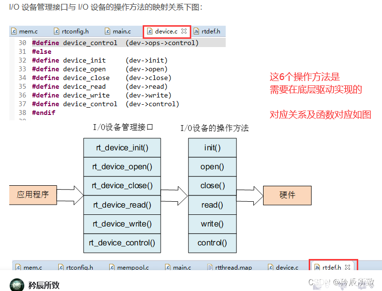
我們通過(guò)前面的 UART 設(shè)備的分析,已經(jīng)知道了設(shè)備的基本的框架了,首先我們來(lái)看一下 上一篇文章講到的 UART 設(shè)備框架:
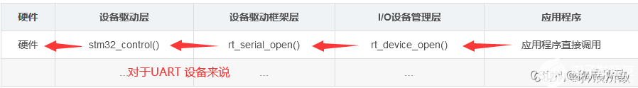
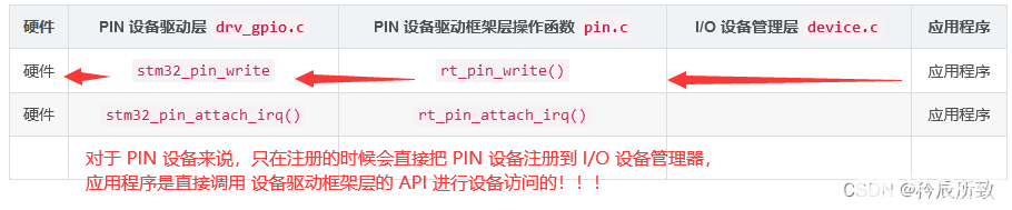
對(duì)于 PIN 設(shè)備來(lái)說(shuō),框架總結(jié)如下圖表:
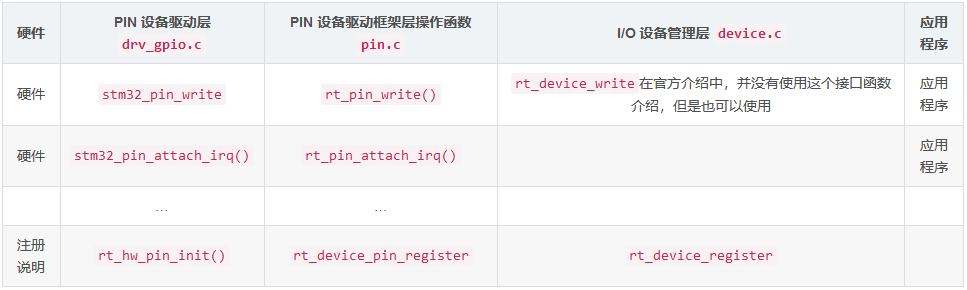
?? 前面一直說(shuō) PIN 設(shè)備有點(diǎn)特別,那只不過(guò)是因?yàn)楣俜秸f(shuō)明中 應(yīng)用程序調(diào)用的不是 I/O 設(shè)備管理層的接口函數(shù),而是直接調(diào)用的 PIN 設(shè)備驅(qū)動(dòng)框架層的接口函數(shù):
知道了這一點(diǎn)的話,其實(shí)我們都不需要進(jìn)行過(guò)多的分析,具體的過(guò)程分析可以查看前面幾篇博文,我們這里只需要對(duì) PIN 設(shè)備驅(qū)動(dòng)框架層 和 設(shè)備驅(qū)動(dòng)層的接口簡(jiǎn)單的了解一下,畢竟 GPIO 的操作還是很簡(jiǎn)單的。
1.3 PIN 設(shè)備驅(qū)動(dòng)框架層
通過(guò)上面的說(shuō)明,我們知道 PIN 設(shè)備的使用是直接調(diào)用的 設(shè)備驅(qū)動(dòng)框架層的接口,所以我們來(lái)看看 PIN 設(shè)備驅(qū)動(dòng)框架層的文件(pin.c)有哪些函數(shù)接口:
實(shí)現(xiàn)的函數(shù)
//私有的
static struct rt_device_pin _hw_pin;
static rt_size_t _pin_read(rt_device_t dev, rt_off_t pos, void *buffer, rt_size_t size)
static rt_size_t _pin_write(rt_device_t dev, rt_off_t pos, const void *buffer, rt_size_t size)
static rt_err_t  _pin_control(rt_device_t dev, int cmd, void *args)

//可調(diào)用的
int rt_device_pin_register(const char *name, const struct rt_pin_ops *ops, void *user_data);

/* Get pin number by name,such as PA.0,P0.12 */
rt_base_t rt_pin_get(const char *name);
void rt_pin_mode(rt_base_t pin, rt_base_t mode);
void rt_pin_write(rt_base_t pin, rt_base_t value);
int  rt_pin_read(rt_base_t pin);
rt_err_t rt_pin_attach_irq(rt_int32_t pin, rt_uint32_t mode,
                             void (*hdr)(void *args), void  *args);
rt_err_t rt_pin_detach_irq(rt_int32_t pin);
rt_err_t rt_pin_irq_enable(rt_base_t pin, rt_uint32_t enabled);
挑一個(gè)函數(shù)簡(jiǎn)單看看:
/* RT-Thread Hardware PIN APIs */
void rt_pin_mode(rt_base_t pin, rt_base_t mode)
{
    RT_ASSERT(_hw_pin.ops != RT_NULL);
    _hw_pin.ops->pin_mode(&_hw_pin.parent, pin, mode);
}
函數(shù)先斷言判斷_hw_pin.ops這個(gè)結(jié)構(gòu)體是否有效,有效的情況下就設(shè)置引腳的模式。
第一個(gè)參數(shù)是引腳的索引號(hào)(這個(gè)在我們下面講解 PIN 設(shè)備驅(qū)動(dòng)層的時(shí)候會(huì)有說(shuō)明什么是索引號(hào)),
第二個(gè)參數(shù)是引腳模式(具體的模式我們也會(huì)再下面講解GPIO 設(shè)置時(shí)候統(tǒng)一說(shuō)明)。
PIN 設(shè)備控制塊
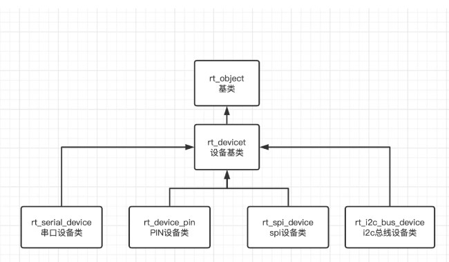
在 RT-Thread 中 PIN 設(shè)備作為一個(gè)對(duì)象,那么肯定有他的對(duì)象控制塊,和我們前面學(xué)習(xí)的所有的對(duì)象一樣,在pin.h中有 PIN 設(shè)備的對(duì)象結(jié)構(gòu)體:
/* pin device and operations for RT-Thread */
struct rt_device_pin
{
    struct rt_device parent;  // rt_device 我們前面講過(guò)的,所有 device 的父類
    const struct rt_pin_ops *ops;
};

struct rt_pin_ops
{
    void (*pin_mode)(struct rt_device *device, rt_base_t pin, rt_base_t mode);
    void (*pin_write)(struct rt_device *device, rt_base_t pin, rt_base_t value);
    int (*pin_read)(struct rt_device *device, rt_base_t pin);

    /* TODO: add GPIO interrupt */
    rt_err_t (*pin_attach_irq)(struct rt_device *device, rt_int32_t pin,
                      rt_uint32_t mode, void (*hdr)(void *args), void *args);
    rt_err_t (*pin_detach_irq)(struct rt_device *device, rt_int32_t pin);
    rt_err_t (*pin_irq_enable)(struct rt_device *device, rt_base_t pin, rt_uint32_t enabled);
    rt_base_t (*pin_get)(const char *name);
};
?? PIN 設(shè)備的訪問(wèn)函數(shù)都是在 PIN 設(shè)備控制塊中的結(jié)構(gòu)體成員 ops 中實(shí)現(xiàn)的,也是通過(guò)這個(gè)結(jié)構(gòu)體成員與 底層驅(qū)動(dòng)層關(guān)聯(lián)起來(lái) —— 在設(shè)備驅(qū)動(dòng)層定義rt_pin_ops類型的變量,實(shí)現(xiàn)這些操作函數(shù)。
注冊(cè)函數(shù)
在 PIN設(shè)備初始化的時(shí)候,rt_hw_pin_init()會(huì)調(diào)用 rt_device_pin_register 函數(shù)進(jìn)行 PIN 設(shè)備的初始化。
PIN 設(shè)備注冊(cè)函數(shù),使用這個(gè)注冊(cè)函數(shù),可以綁定底層驅(qū)動(dòng)層的函數(shù),也同時(shí)將設(shè)備接口提供給上層 I/O 設(shè)備管理層:
int rt_device_pin_register(const char *name, const struct rt_pin_ops *ops, void *user_data)
{
    _hw_pin.parent.type         = RT_Device_Class_Miscellaneous;
    _hw_pin.parent.rx_indicate  = RT_NULL;
    _hw_pin.parent.tx_complete  = RT_NULL;

#ifdef RT_USING_DEVICE_OPS
    _hw_pin.parent.ops          = &pin_ops;
#else
    _hw_pin.parent.init         = RT_NULL; //PIN 設(shè)備不需要
    _hw_pin.parent.open         = RT_NULL; //
    _hw_pin.parent.close        = RT_NULL; //
    _hw_pin.parent.read         = _pin_read; //* 把設(shè)備的read操作綁定在pin.c的_pin_read函數(shù) */
    _hw_pin.parent.write        = _pin_write; //同上
    _hw_pin.parent.control      = _pin_control; //同上
#endif
	/*
	把drv_gpio.c所實(shí)現(xiàn)的_stm32_pin_ops綁定在_hw_pin.ops上
	因?yàn)?PIN 設(shè)備驅(qū)動(dòng)層使用的注冊(cè)函數(shù)為:
	rt_device_pin_register("pin", &_stm32_pin_ops, RT_NULL);
	*/
    _hw_pin.ops                 = ops;
    _hw_pin.parent.user_data    = user_data;

    /*
    register a character device
    /* 將其注冊(cè)進(jìn)device設(shè)備框架中 */
    */
    rt_device_register(&_hw_pin.parent, name, RT_DEVICE_FLAG_RDWR);

    return 0;
}
在注冊(cè)函數(shù)中:_hw_pin.ops = ops; 這個(gè)操作就把設(shè)備驅(qū)動(dòng)層實(shí)現(xiàn)的硬件操作函數(shù)給關(guān)聯(lián)到了 設(shè)備驅(qū)動(dòng)框架層。
官方說(shuō)明的 PIN 設(shè)備訪問(wèn)的接口就是在 設(shè)備驅(qū)動(dòng)框架層 提供的函數(shù)接口。
但是我們看到:
    _hw_pin.parent.read         = _pin_read; //把設(shè)備的read操作綁定在pin.c的_pin_read函數(shù)
    _hw_pin.parent.write        = _pin_write;
    _hw_pin.parent.control      = _pin_control;
這說(shuō)明我們不僅可以使用 rt_pin_read 獲取 PIN 設(shè)備的值,還可以使用 rt_device_read 獲取 PIN 設(shè)備的值!!!
?? 在 RT-Thread 的 PIN 設(shè)備模型中, rt_pin_read 函數(shù)和 rt_device_read 函數(shù)效果一樣。
1.4 PIN 設(shè)備驅(qū)動(dòng)層
PIN 設(shè)備驅(qū)動(dòng)層,直接與硬件打交道的層面,對(duì)于我們使用的 STM32 來(lái)說(shuō),里面的很多操作我們應(yīng)該都不會(huì)陌生,我們也簡(jiǎn)單了解下里面的函數(shù),主要的目的在于實(shí)現(xiàn) PIN 設(shè)備控制塊中 rt_pin_ops 成員中的幾個(gè)函數(shù):
實(shí)現(xiàn)的函數(shù)
static const struct pin_index *get_pin(uint8_t pin)
static void stm32_pin_write(rt_device_t dev, rt_base_t pin, rt_base_t value)
static int stm32_pin_read(rt_device_t dev, rt_base_t pin)
static void stm32_pin_mode(rt_device_t dev, rt_base_t pin, rt_base_t mode)

rt_inline rt_int32_t bit2bitno(rt_uint32_t bit)
rt_inline const struct pin_irq_map *get_pin_irq_map(uint32_t pinbit)

static rt_err_t stm32_pin_attach_irq(struct rt_device *device, rt_int32_t pin,
                                     rt_uint32_t mode, void (*hdr)(void *args), void *args)
static rt_err_t stm32_pin_dettach_irq(struct rt_device *device, rt_int32_t pin)
static rt_err_t stm32_pin_irq_enable(struct rt_device *device, rt_base_t pin,
                                     rt_uint32_t enabled)

/*一個(gè)重要的結(jié)構(gòu)體*/
const static struct rt_pin_ops _stm32_pin_ops =
{
    stm32_pin_mode,
    stm32_pin_write,
    stm32_pin_read,
    stm32_pin_attach_irq,
    stm32_pin_dettach_irq,
    stm32_pin_irq_enable,
};

rt_inline void pin_irq_hdr(int irqno)

void HAL_GPIO_EXTI_Callback(uint16_t GPIO_Pin)
void EXTI0_IRQHandler(void)
...//一系列的外部中斷函數(shù)
...
int rt_hw_pin_init(void)
我們簡(jiǎn)單來(lái)看一個(gè)函數(shù),根本不需要過(guò)多的解釋:
static void stm32_pin_write(rt_device_t dev, rt_base_t pin, rt_base_t value)
{
    const struct pin_index *index;

    index = get_pin(pin);
    if (index == RT_NULL)
    {
        return;
    }

    HAL_GPIO_WritePin(index->gpio, index->pin, (GPIO_PinState)value);
}
初始化函數(shù)
初始化函數(shù)雖然重要,但是簡(jiǎn)單,看一下就能明白,首先就是熟悉的 GPIO 時(shí)鐘初始化,
然后就是調(diào)用設(shè)備注冊(cè)函數(shù),設(shè)備名稱 pin ,也是在這里定義的,如果改成其他的,在 shell 工具中使用 list_device 就會(huì)顯示其他的名稱了。
第二個(gè)參數(shù),就是將設(shè)備驅(qū)動(dòng)層中實(shí)現(xiàn)的對(duì)硬件的操作函數(shù)關(guān)聯(lián)到 PIN 設(shè)備驅(qū)動(dòng)框架層以供應(yīng)用程序使用用。
int rt_hw_pin_init(void)
{
#if defined(__HAL_RCC_GPIOA_CLK_ENABLE)
    __HAL_RCC_GPIOA_CLK_ENABLE();
#endif

#if defined(__HAL_RCC_GPIOB_CLK_ENABLE)
    __HAL_RCC_GPIOB_CLK_ENABLE();
#endif

#if defined(__HAL_RCC_GPIOC_CLK_ENABLE)
    __HAL_RCC_GPIOC_CLK_ENABLE();
#endif

#if defined(__HAL_RCC_GPIOD_CLK_ENABLE)
    __HAL_RCC_GPIOD_CLK_ENABLE();
#endif

#if defined(__HAL_RCC_GPIOE_CLK_ENABLE)
    __HAL_RCC_GPIOE_CLK_ENABLE();
#endif

#if defined(__HAL_RCC_GPIOF_CLK_ENABLE)
    __HAL_RCC_GPIOF_CLK_ENABLE();
#endif

#if defined(__HAL_RCC_GPIOG_CLK_ENABLE)
    #ifdef SOC_SERIES_STM32L4
        HAL_PWREx_EnableVddIO2();
    #endif
    __HAL_RCC_GPIOG_CLK_ENABLE();
#endif

#if defined(__HAL_RCC_GPIOH_CLK_ENABLE)
    __HAL_RCC_GPIOH_CLK_ENABLE();
#endif

#if defined(__HAL_RCC_GPIOI_CLK_ENABLE)
    __HAL_RCC_GPIOI_CLK_ENABLE();
#endif

#if defined(__HAL_RCC_GPIOJ_CLK_ENABLE)
    __HAL_RCC_GPIOJ_CLK_ENABLE();
#endif

#if defined(__HAL_RCC_GPIOK_CLK_ENABLE)
    __HAL_RCC_GPIOK_CLK_ENABLE();
#endif

    return rt_device_pin_register("pin", &_stm32_pin_ops, RT_NULL);
}
☆引腳定義☆
在驅(qū)動(dòng)文件中,關(guān)于 GPIO 引腳的定義方式(STM32為例),我們有必要說(shuō)明一下。
與 UART 不同的是,GPIO 配置簡(jiǎn)單能夠更直接關(guān)聯(lián)硬件,所以 HAL 庫(kù)并沒有為 GPIO 提供句柄結(jié)構(gòu)體描述,在 HAL 庫(kù)中描述 GPIO 使用了兩個(gè)參數(shù):GPIO_TypeDef* GPIOx和GPIO_Pin,比如:
GPIO_PinState     HAL_GPIO_ReadPin(GPIO_TypeDef* GPIOx, uint16_t GPIO_Pin);
void              HAL_GPIO_WritePin(GPIO_TypeDef* GPIOx, uint16_t GPIO_Pin, GPIO_PinState PinState);

void              HAL_GPIO_TogglePin(GPIO_TypeDef* GPIOx, uint16_t GPIO_Pin);
而在 RT-Thread 中,其定義了一個(gè)結(jié)構(gòu)體 pin_index,通過(guò)一個(gè)變量即可描述一個(gè) GPIO,如下:
/* STM32 GPIO driver */
struct pin_index
{
    int index;
    GPIO_TypeDef *gpio;
    uint32_t pin;
};
針對(duì)這個(gè)結(jié)構(gòu)體,驅(qū)動(dòng)程序中給了一些補(bǔ)充的操作:
/*
相當(dāng)于結(jié)構(gòu)體pin_index以宏定義的形式被初始化
用C語(yǔ)言字符串連接定義引腳信息
index 引腳的索引號(hào),用戶可自行定義的驅(qū)動(dòng)程序定義的引腳編號(hào)
gpio 相當(dāng)于HAL庫(kù)中的GPIO_TypeDef
gpio_index 相當(dāng)于HAL庫(kù)中的GPIO_Pin
例如宏__STM32_PIN(0, A, 0) 就表示結(jié)構(gòu)體內(nèi)容為 {0, GPIOA, GPIO_PIN_0}
*/
#define __STM32_PIN(index, gpio, gpio_index) \
{ \
index, GPIO##gpio, GPIO_PIN_##gpio_index \
}
//保留未使用的宏定義,有些IO口未使用,使用這個(gè)宏定義
#define __STM32_PIN_RESERVE \
{ \
-1, 0, 0 \
}
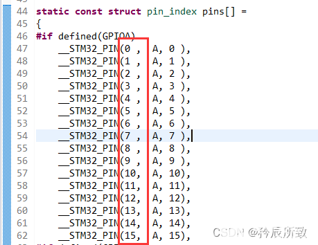
static const struct pin_index pins[] =
{
#if defined(GPIOA)
__STM32_PIN(0 , A, 0 ),
__STM32_PIN(1 , A, 1 ),
__STM32_PIN(2 , A, 2 ),
__STM32_PIN(3 , A, 3 ),
__STM32_PIN(4 , A, 4 ),
__STM32_PIN(5 , A, 5 ),
__STM32_PIN(6 , A, 6 ),
__STM32_PIN(7 , A, 7 ),
__STM32_PIN(8 , A, 8 ),
__STM32_PIN(9 , A, 9 ),
__STM32_PIN(10, A, 10),
__STM32_PIN(11, A, 11),
__STM32_PIN(12, A, 12),
__STM32_PIN(13, A, 13),
__STM32_PIN(14, A, 14),
__STM32_PIN(15, A, 15),
#if defined(GPIOB)
__STM32_PIN(16, B, 0),
__STM32_PIN(17, B, 1),
//后面省略很多......
首先宏定義#define __STM32_PIN(index, gpio, gpio_index) :
其中##為C語(yǔ)言連接符,其功能是在帶參數(shù)的宏定義中將兩個(gè)子串(token)聯(lián)接起來(lái),從而形成一個(gè)新的子串,例如宏__STM32_PIN(0, A, 0) 就表示結(jié)構(gòu)體內(nèi)容為 {0, GPIOA, GPIO_PIN_0},就等于定義了一個(gè)pin_index結(jié)構(gòu)體。
然后宏定義__STM32_PIN_RESERVE :
預(yù)留的IO樓,有些IO口未使用,使用這個(gè)宏定義
接下來(lái)的結(jié)構(gòu)體數(shù)組pins :
pins 為pin_index結(jié)構(gòu)體類型的數(shù)組,RT-Thread 使用 pins 數(shù)組對(duì) 所有的 GPIO 引腳進(jìn)行初始化定義。
這樣就相當(dāng)于芯片上所支持的 IO 口都進(jìn)行了初始化定義,每一個(gè) GPIO 都有了一個(gè)對(duì)應(yīng)的索引號(hào)index。
在 RT-Thread 提供的 PIN 設(shè)備操作函數(shù)中void rt_pin_mode(rt_base_t pin, rt_base_t mode);, 他的第一個(gè)參數(shù)也不是類似 PIN設(shè)備控制塊之類的數(shù)據(jù)結(jié)構(gòu),而是一個(gè)引腳索引號(hào),就是對(duì)應(yīng)的上面這個(gè)index。
引腳中斷的分析和 引腳定義類似,可自行查看代碼,這里就不過(guò)多說(shuō)明。
二、PIN 設(shè)備操作函數(shù)
文章開頭我們雖然已經(jīng)認(rèn)識(shí)過(guò) PIN 設(shè)備的操作函數(shù),但是我們沒有對(duì)函數(shù)參數(shù)可取值做說(shuō)明,學(xué)習(xí) API 的使用還是老樣子,直接放函數(shù)原型然后看注釋。
2.1 獲取 PIN 索引號(hào)方法
在我們使用某個(gè) GPIO 的時(shí)候,第一步要做的就是獲取 GPIO 的索引號(hào),即上文說(shuō)到的index。因?yàn)閷?duì) PIN 設(shè)備的訪問(wèn)操作都是通過(guò)這個(gè)索引號(hào)進(jìn)行的。
在 RT-Thread 中,提供了 3種方式獲取 PIN 設(shè)備索引號(hào):
方法一: 使用函數(shù)rt_pin_get():
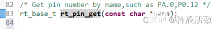
在 pin.c 文件中提供了一個(gè)函數(shù):
rt_base_t rt_pin_get(const char *name)
里面的參數(shù)為一個(gè)名字,那么這個(gè)名字是什么呢?在函數(shù)申明有注釋:
對(duì)于STM32而言,使用示例如下:
//獲取索引號(hào)
pin_number = rt_pin_get("PA.9"); // pin_number 就是索引號(hào)
//設(shè)置GPIO模式
rt_pin_mode(pin_number , PIN_MODE_INPUT_PULLUP);
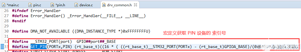
方法二: 使用宏定義GET_PIN:
在drv_common.h文件中有宏定義,可以直接獲取 GPIO 的索引號(hào):
#define __STM32_PORT(port)  GPIO##port##_BASE
#define GET_PIN(PORTx,PIN) (rt_base_t)((16 * ( ((rt_base_t)__STM32_PORT(PORTx) - (rt_base_t)GPIOA_BASE)/(0x0400UL) )) + PIN)
對(duì)于STM32而言,使用示例如下:
//獲取索引號(hào)
#define LED0_PIN        GET_PIN(B,  9)

//LED0 點(diǎn)亮或者熄滅
#define LED0(n)	(n ? rt_pin_write(LED0_PIN, PIN_HIGH) : rt_pin_write(LED0_PIN, PIN_LOW))
方法三: 查看驅(qū)動(dòng)文件drv_gpio.c:
上面講解 PIN 設(shè)備驅(qū)動(dòng)層的時(shí)候說(shuō)到過(guò),所有的 GPIO 對(duì)應(yīng)的索引號(hào)都會(huì)在驅(qū)動(dòng)文件中定義,直接查看文件使用索引號(hào)就可以:
對(duì)于STM32而言,使用示例如下:
//對(duì)應(yīng)驅(qū)動(dòng)文件,下面的代碼含義就是 設(shè)置 PA0 的模式為 PIN_MODE_INPUT_PULLUP
rt_pin_mode(0, PIN_MODE_INPUT_PULLUP);
說(shuō)明,查看驅(qū)動(dòng)文件的方式并不直觀。
2.2 操作函數(shù)
操作函數(shù)說(shuō)明老樣子
2.2.1 設(shè)置 GPIO 模式
/*
參數(shù) 	描述
pin 	引腳編號(hào):索引號(hào)
mode 	引腳工作模式

工作模式可選:
#define PIN_MODE_OUTPUT 0x00            	輸出
#define PIN_MODE_INPUT 0x01              	輸入
#define PIN_MODE_INPUT_PULLUP 0x02      	上拉輸入
#define PIN_MODE_INPUT_PULLDOWN 0x03    	下拉輸入
#define PIN_MODE_OUTPUT_OD 0x04         	 開漏輸出
*/
void rt_pin_mode(rt_base_t pin, rt_base_t mode);
2.2.2 設(shè)置/ 讀取 GPIO 電平
設(shè)置引腳電平:
/*
參數(shù) 	描述
pin 	引腳編號(hào)
value 	電平邏輯值,

value 	取值:
PIN_LOW 低電平,
PIN_HIGH 高電平
*/
void rt_pin_write(rt_base_t pin, rt_base_t value);
讀取引腳電平:
/*
參數(shù) 	描述
pin 	引腳編號(hào)
返回
PIN_LOW 	低電平
PIN_HIGH 	高電平
*/
int  rt_pin_read(rt_base_t pin);
2.2.3 綁定/脫離中斷回調(diào)函數(shù)
綁定中斷回調(diào)函數(shù):
/*
參數(shù) 	描述
pin 	引腳編號(hào)
mode 	中斷觸發(fā)模式
hdr 	中斷回調(diào)函數(shù),用戶需要自行定義這個(gè)函數(shù)
args 	中斷回調(diào)函數(shù)的參數(shù),不需要時(shí)設(shè)置為 RT_NULL
返回 	——
RT_EOK 	綁定成功
錯(cuò)誤碼 	綁定失敗

其中 mode 可選參數(shù):
#define PIN_IRQ_MODE_RISING 		0x00    上升沿觸發(fā)
#define PIN_IRQ_MODE_FALLING 		0x01    下降沿觸發(fā)
#define PIN_IRQ_MODE_RISING_FALLING 0x02 	邊沿觸發(fā)(上升沿和下降沿都觸發(fā))
#define PIN_IRQ_MODE_HIGH_LEVEL 	0x03    	高電平觸發(fā)
#define PIN_IRQ_MODE_LOW_LEVEL 		0x04      	低電平觸發(fā)
*/
rt_err_t rt_pin_attach_irq(rt_int32_t pin, rt_uint32_t mode,
                             void (*hdr)(void *args), void  *args);
脫離中斷回調(diào)函數(shù):
/*
參數(shù) 	描述
pin 	引腳編號(hào)
返回 	——
RT_EOK 	脫離成功
錯(cuò)誤碼 	脫離失敗
*/
rt_err_t rt_pin_detach_irq(rt_int32_t pin);
說(shuō)明:引腳脫離了中斷回調(diào)函數(shù)以后,中斷并沒有關(guān)閉,還可以調(diào)用綁定中斷回調(diào)函數(shù)再次綁定其他回調(diào)函數(shù)。
2.2.4 使能中斷
綁定好引腳中斷回調(diào)函數(shù)后需要使用下面的函數(shù)使能引腳中斷:
/*
參數(shù) 	描述
pin 		引腳編號(hào)
enabled 	狀態(tài)
返回 	——
RT_EOK 	使能成功
錯(cuò)誤碼 	使能失敗

enabled 	可取 2 種值之一:
PIN_IRQ_ENABLE	(開啟)
PIN_IRQ_DISABLE	(關(guān)閉)
*/
rt_err_t rt_pin_irq_enable(rt_base_t pin, rt_uint32_t enabled);
三、PIN 設(shè)備示例
只要明白了PIN 設(shè)備模型原理,使用起來(lái)還是很簡(jiǎn)單的,我們先看一下原理圖:
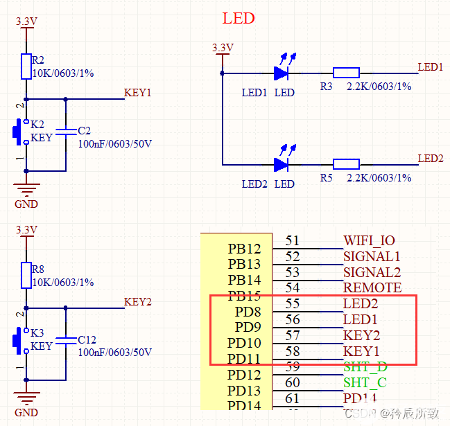
程序如下,測(cè)試OK,太簡(jiǎn)單所以沒有什么好說(shuō)的:
...
//添加這兩個(gè)頭文件
#include
#include "board.h"
...

static struct rt_thread led1_thread;    //led1線程
static char led1_thread_stack[256];

static rt_thread_t key1_thread = RT_NULL; //

#define LED1_PIN        GET_PIN(D,  9)
#define LED2_PIN        GET_PIN(D,  8)
#define KEY1_PIN        GET_PIN(D,  11)
#define KEY2_PIN        GET_PIN(D,  10)

#define key1_read   rt_pin_read(KEY1_PIN)
#define LED1_ON     rt_pin_write(LED1_PIN, PIN_LOW);
#define LED1_OFF    rt_pin_write(LED1_PIN, PIN_HIGH);
#define LED2_ON     rt_pin_write(LED2_PIN, PIN_LOW);
#define LED2_OFF    rt_pin_write(LED2_PIN, PIN_HIGH);
//#define LED0(n) (n ? rt_pin_write(LED0_PIN, PIN_HIGH) : rt_pin_write(LED0_PIN, PIN_LOW))

static void led1_thread_entry(void *par){
    while(1){
        LED1_ON;
        rt_thread_mdelay(1000);
        LED1_OFF;
        rt_thread_mdelay(1000);
    }
}

static void key1_thread_entry(void *par){
    while(1){
        if(key1_read == 0){
            rt_thread_mdelay(10); //去抖動(dòng)
            if(key1_read == 0){
                rt_kprintf("key1 kicked..\r\n");
             }
             while(key1_read == 0){rt_thread_mdelay(10);//去抖動(dòng)
            }
        }
        rt_thread_mdelay(1);
   }
}

int main(void)
{

    MX_USART1_UART_Init();
    //    MX_GPIO_Init();  //使用設(shè)備模型不需要初始化這個(gè)
    /*配置LED管腳為輸出*/
    rt_pin_mode(LED1_PIN, PIN_MODE_OUTPUT);
    rt_pin_mode(LED2_PIN, PIN_MODE_OUTPUT);
    /*配置按鍵為輸入*/
    rt_pin_mode(KEY1_PIN, PIN_MODE_INPUT);
    rt_pin_mode(KEY2_PIN, PIN_MODE_INPUT);
    /*LED默認(rèn)狀態(tài)*/
    rt_pin_write(LED1_PIN, 1);
    rt_pin_write(LED2_PIN, 0);

	rt_err_t rst2;
    rst2 = rt_thread_init(&led1_thread,
                        "led1_blink ",
                        led1_thread_entry,
                        RT_NULL,
                        &led1_thread_stack[0],
                        sizeof(led1_thread_stack),
                        RT_THREAD_PRIORITY_MAX -1,
                        50);

    if(rst2 == RT_EOK){
        rt_thread_startup(&led1_thread);
    }

    key1_thread = rt_thread_create("key1_control",
                                key1_thread_entry,
                                RT_NULL,
                                512,
                                RT_THREAD_PRIORITY_MAX -2,
                                50);

        /* 如果獲得線程控制塊,啟動(dòng)這個(gè)線程 */
        if (key1_thread != RT_NULL)
            rt_thread_startup(key1_thread);

  ...//后面省略
結(jié)語(yǔ)
本文我們?cè)敿?xì)的分析了 RT-Thread I/O 設(shè)備模型之PIN設(shè)備,最終看來(lái),使用 PIN 設(shè)備模型操作還是特別的簡(jiǎn)單的。
其實(shí)關(guān)鍵的部分還是在于理解 PIN 設(shè)備模型的原理,理解了以后使用起來(lái)也更加的得心應(yīng)手。
GPIO設(shè)備雖然簡(jiǎn)單,但是文章寫下來(lái)也1W多字了,即便以前對(duì) PIN 設(shè)備有點(diǎn)模糊,只要看了本文,相信大家肯定有撥云見日的感覺!
希望大家多多支持!本文就到這里,謝謝!
審核編輯:湯梓紅
-
GPIO
+關(guān)注
關(guān)注
16文章
1264瀏覽量
53504 -
PIN
+關(guān)注
關(guān)注
1文章
311瀏覽量
25151 -
RT-Thread
+關(guān)注
關(guān)注
32文章
1366瀏覽量
41485
發(fā)布評(píng)論請(qǐng)先 登錄
RT-Thread記錄(十、全面認(rèn)識(shí) I/O 設(shè)備模型)
RT-Thread記錄(十一、UART設(shè)備—源碼解析)
RT-Thread記錄(十四、I/O 設(shè)備模型之ADC設(shè)備)

RT-Thread記錄(十二、UART設(shè)備—使用測(cè)試)

RT-Thread記錄(十五、I/O 設(shè)備模型之SPI設(shè)備)
RT-Thread 的 IO 設(shè)備模型框架是由哪些部分組成的呢
【原創(chuàng)精選】RT-Thread征文精選技術(shù)文章合集
RT-Thread設(shè)備模型框架及創(chuàng)建注冊(cè)設(shè)備的實(shí)現(xiàn)


 工商網(wǎng)監(jiān)
評(píng)論